
How to Use Adafruit FT232H Breakout: Examples, Pinouts, and Specs
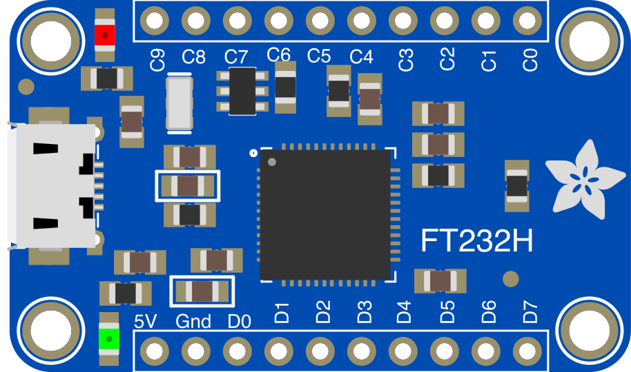
 Design with Adafruit FT232H Breakout in Cirkit Designer
Introduction
The Adafruit FT232H Breakout (Manufacturer Part ID: 2264) is a versatile USB-to-serial converter designed to facilitate communication between a computer and various electronic devices. It features support for multiple protocols, including I2C, SPI, and UART, making it an essential tool for prototyping, debugging, and interfacing with sensors, displays, and other peripherals. Additionally, the breakout board includes multiple GPIO pins, enabling it to act as a general-purpose USB-to-GPIO bridge.
Explore Projects Built with Adafruit FT232H Breakout
 Open Project in Cirkit Designer
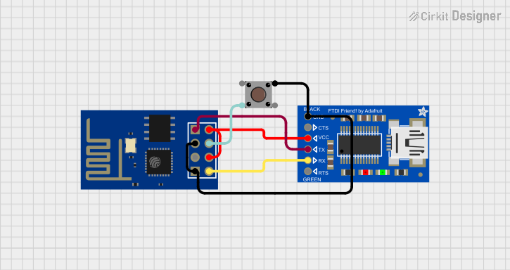 Open Project in Cirkit Designer
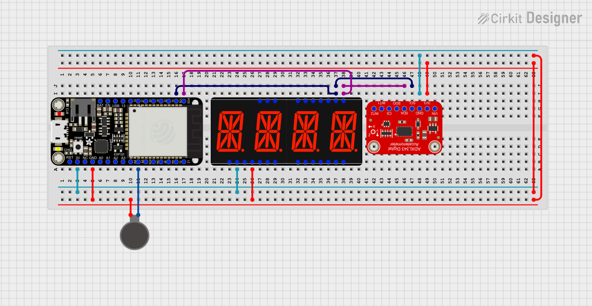 Open Project in Cirkit Designer
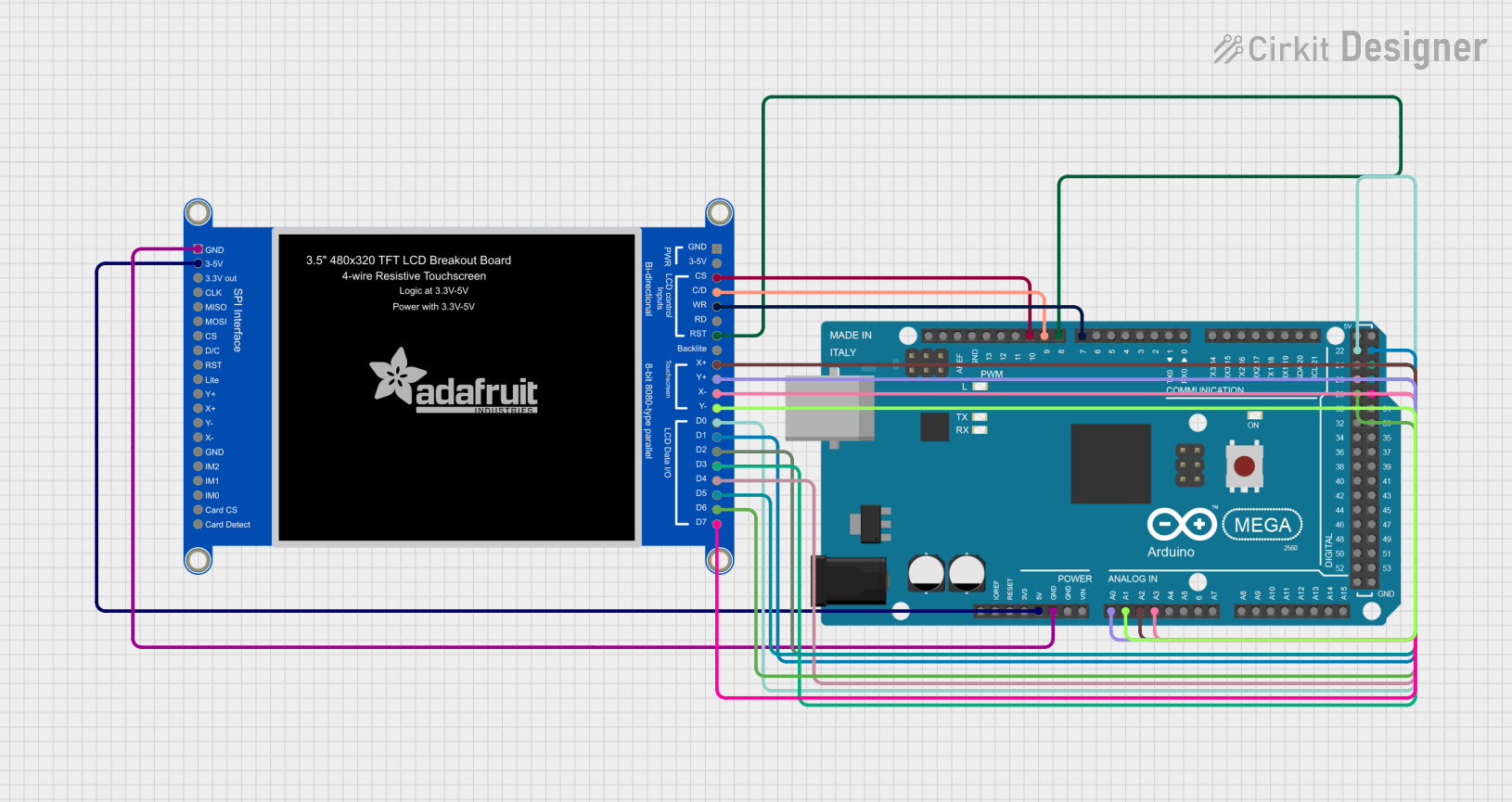 Open Project in Cirkit Designer
Explore Projects Built with Adafruit FT232H Breakout
Open Project in Cirkit DesignerOpen Project in Cirkit DesignerOpen Project in Cirkit DesignerOpen Project in Cirkit DesignerCommon Applications and Use Cases
- Interfacing with I2C or SPI sensors and devices via USB.
- Debugging UART-based communication.
- Acting as a USB-to-GPIO bridge for controlling LEDs, relays, or other components.
- Programming or testing microcontrollers and other embedded systems.
- Rapid prototyping for projects requiring USB connectivity.
Technical Specifications
The Adafruit FT232H Breakout is built around the FTDI FT232H chip, which provides robust and reliable USB-to-serial communication. Below are the key technical details:
General Specifications
| Parameter | Value |
|---|---|
| USB Interface | USB 2.0 Full-Speed |
| Supported Protocols | I2C, SPI, UART, GPIO |
| GPIO Voltage Levels | 3.3V (5V-tolerant inputs) |
| Operating Voltage | 3.3V (regulated from USB 5V) |
| Current Consumption | ~50mA (varies based on usage) |
| Dimensions | 22mm x 35mm |
Pin Configuration and Descriptions
The Adafruit FT232H Breakout features a 16-pin header for interfacing with external devices. Below is the pinout:
| Pin Name | Description |
|---|---|
| GND | Ground connection |
| 3V3 | 3.3V output (regulated from USB 5V) |
| 5V | USB 5V power output |
| D0 | GPIO or SPI/I2C/UART data pin (configurable) |
| D1 | GPIO or SPI/I2C/UART data pin (configurable) |
| D2 | GPIO or SPI/I2C/UART data pin (configurable) |
| D3 | GPIO or SPI/I2C/UART data pin (configurable) |
| D4 | GPIO or SPI/I2C/UART data pin (configurable) |
| D5 | GPIO or SPI/I2C/UART data pin (configurable) |
| D6 | GPIO or SPI/I2C/UART data pin (configurable) |
| D7 | GPIO or SPI/I2C/UART data pin (configurable) |
| C0 | GPIO or SPI/I2C/UART data pin (configurable) |
| C1 | GPIO or SPI/I2C/UART data pin (configurable) |
| C2 | GPIO or SPI/I2C/UART data pin (configurable) |
| C3 | GPIO or SPI/I2C/UART data pin (configurable) |
| RESET | Reset pin (active low) |
Usage Instructions
The Adafruit FT232H Breakout is easy to use and can be configured for various communication protocols. Below are the steps to get started:
1. Installing Drivers and Libraries
- Install FTDI Drivers: Download and install the FTDI drivers from the FTDI website.
- Install Adafruit Libraries: If using Python, install the
Adafruit Blinkalibrary, which provides CircuitPython support for the FT232H. Use the following command:pip install adafruit-blinka
2. Connecting the FT232H Breakout
- Connect the FT232H Breakout to your computer using a USB cable.
- Use jumper wires to connect the breakout board to your target device. Ensure proper connections for power, ground, and communication pins (e.g., I2C SDA/SCL or SPI MOSI/MISO/CLK).
3. Using the FT232H with I2C
Below is an example of using the FT232H Breakout to communicate with an I2C device (e.g., a temperature sensor) using Python:
import board
import busio
from adafruit_bus_device.i2c_device import I2CDevice
Create an I2C bus object using the FT232H breakout
i2c = busio.I2C(board.SCL, board.SDA)
Define the I2C address of the target device
DEVICE_ADDRESS = 0x48 # Replace with your device's address
Create an I2C device instance
device = I2CDevice(i2c, DEVICE_ADDRESS)
Read data from the I2C device
with device: buffer = bytearray(2) # Buffer to store received data device.readinto(buffer) # Read 2 bytes from the device print("Received data:", buffer)
4. Important Considerations and Best Practices
- Voltage Levels: The GPIO pins operate at 3.3V logic levels but are 5V-tolerant. Ensure compatibility with your target device.
- Power Supply: The breakout board is powered via USB. If powering external devices, ensure the total current draw does not exceed the USB port's limit.
- Protocol Selection: Configure the FT232H for the desired protocol (I2C, SPI, or UART) using the appropriate software libraries.
Troubleshooting and FAQs
Common Issues and Solutions
FT232H Not Detected by Computer
- Ensure the USB cable is properly connected and functional.
- Verify that the FTDI drivers are correctly installed.
I2C or SPI Communication Fails
- Double-check the wiring and ensure proper pull-up resistors are used for I2C.
- Verify the target device's address and communication settings.
GPIO Pins Not Responding
- Ensure the pins are correctly configured in your software.
- Check for any short circuits or incorrect connections.
Power Issues
- Ensure the total current draw of connected devices does not exceed the USB port's capacity.
FAQs
Q: Can the FT232H Breakout be used with Arduino?
A: The FT232H is primarily designed for use with computers and is not directly compatible with Arduino IDE. However, it can interface with Arduino boards via UART, I2C, or SPI.
Q: Does the FT232H support 5V logic?
A: The GPIO pins operate at 3.3V logic levels but are 5V-tolerant on the inputs.
Q: Can I use the FT232H for programming microcontrollers?
A: Yes, the FT232H can be used as a USB-to-UART bridge for programming microcontrollers that support UART-based bootloading.
By following this documentation, you can effectively utilize the Adafruit FT232H Breakout for a wide range of applications.