How to Use Sensor NTC LM393: Examples, Pinouts, and Specs
Introduction
The Sensor NTC LM393 is a temperature sensing device that utilizes a Negative Temperature Coefficient (NTC) thermistor to measure temperature changes. The LM393 component of the sensor is a dual differential comparator integrated circuit, which is used to compare the voltage level from the NTC thermistor with a reference voltage. This sensor is widely used in applications such as temperature monitoring systems, environmental controls, and electronic thermometers due to its sensitivity and quick response to temperature changes.
Explore Projects Built with Sensor NTC LM393
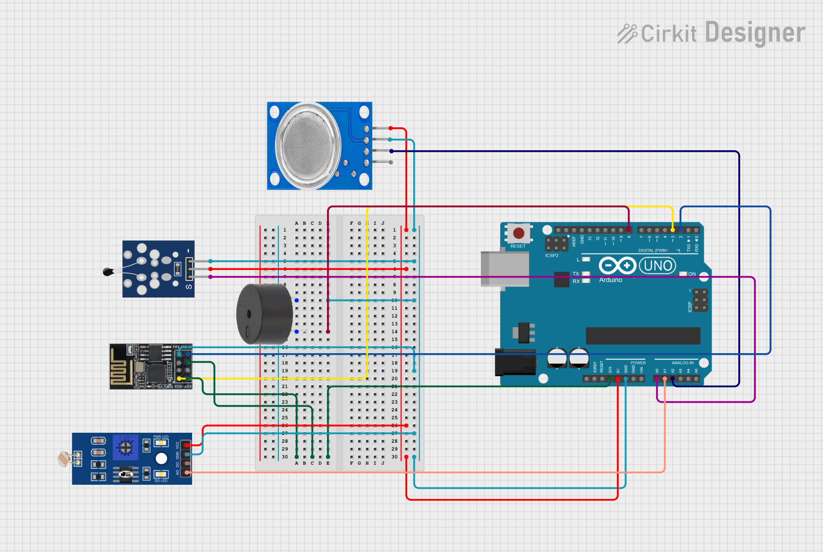
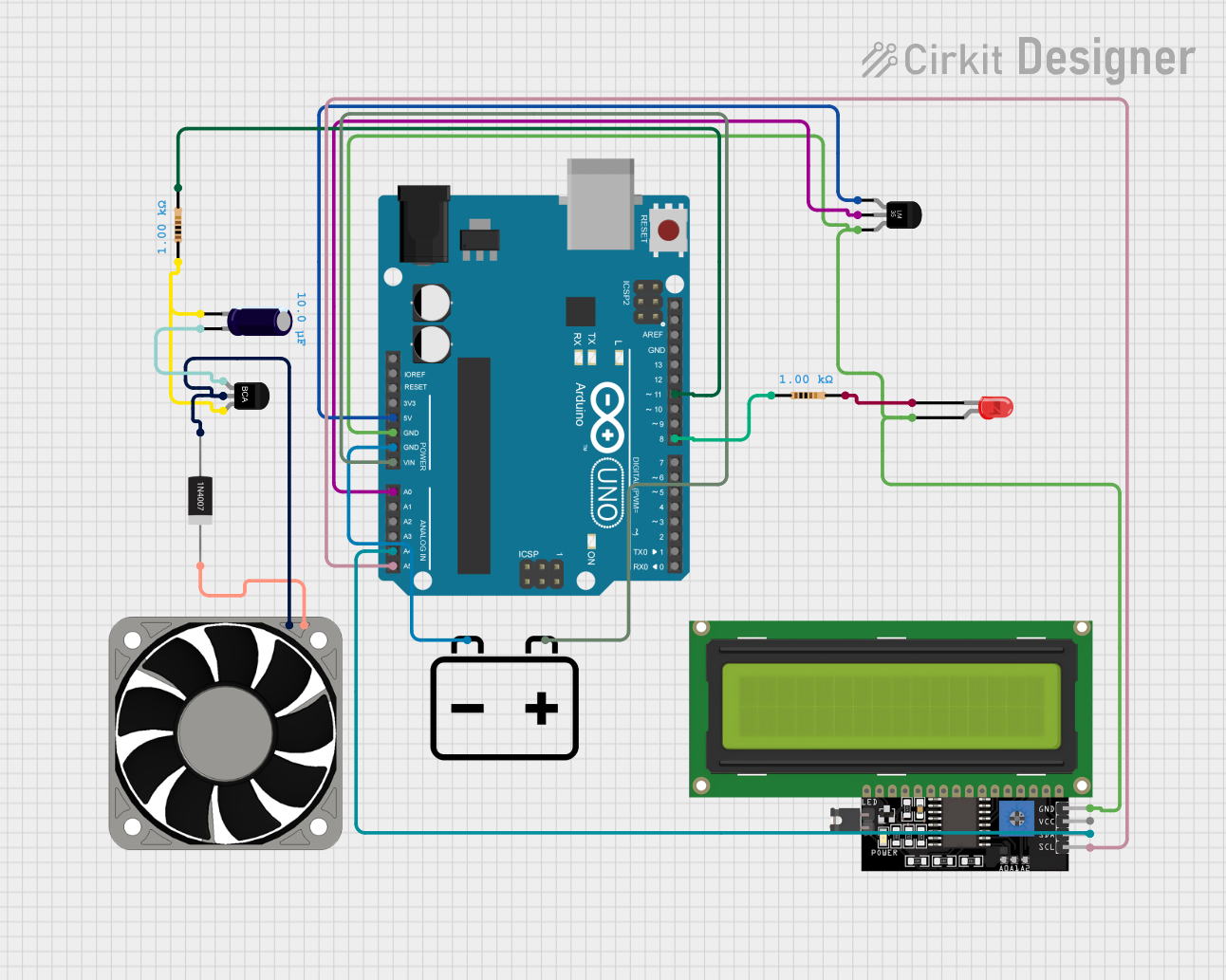
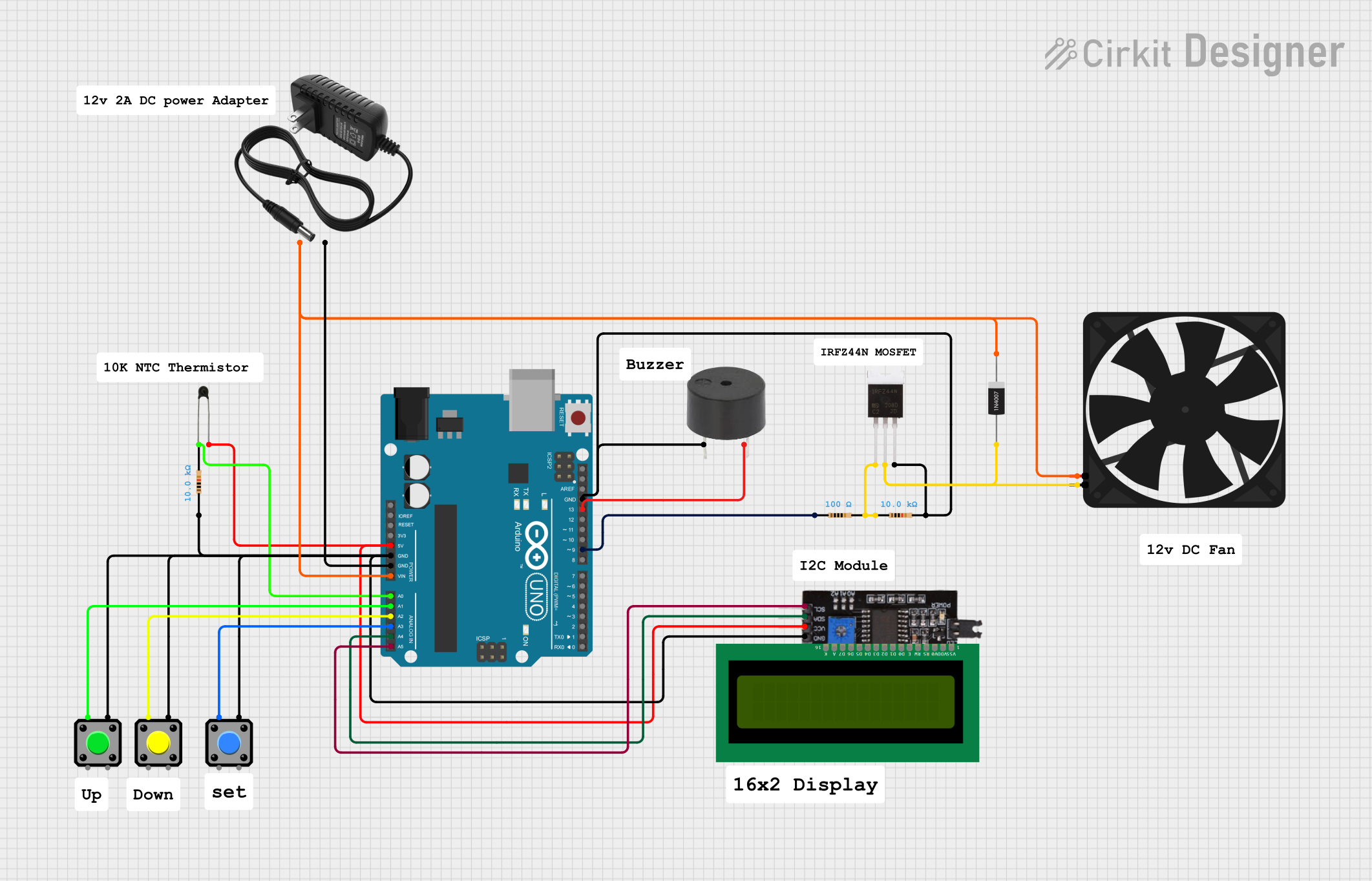
Explore Projects Built with Sensor NTC LM393
Technical Specifications
Key Technical Details
- Operating Voltage (Vcc): 3.3V to 5V
- Temperature Measurement Range: Typically -55°C to 150°C (dependent on the NTC thermistor used)
- Output Type: Digital (comparator output)
- Comparator IC: LM393
- Accuracy: Dependent on the NTC thermistor and external circuitry
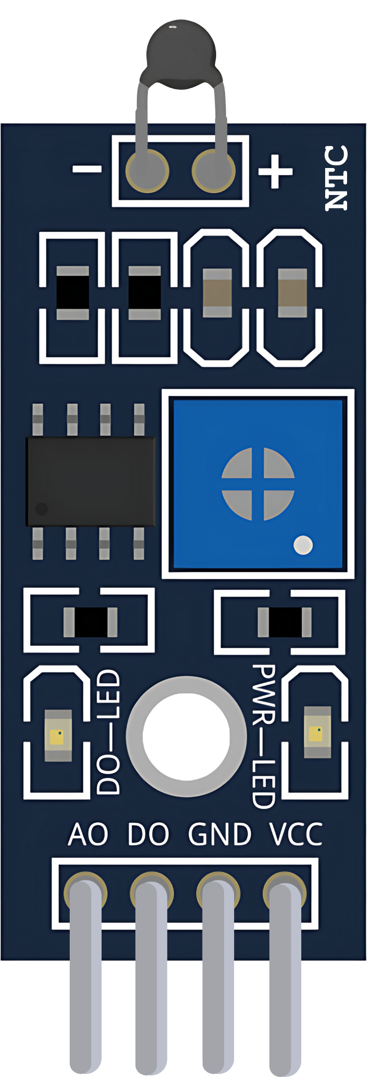
Pin Configuration and Descriptions
| Pin Number | Description |
|---|---|
| 1 | Vcc (Power Supply) |
| 2 | GND (Ground) |
| 3 | DO (Digital Output) |
| 4 | AO (Analog Output from NTC) |
| 5 | Thermistor Input (+) |
| 6 | Reference Voltage Input (-) |
Usage Instructions
How to Use the Sensor in a Circuit
- Power Supply: Connect the Vcc pin to a 3.3V or 5V power supply and the GND pin to the ground of your circuit.
- Output Connections: The DO pin provides a digital output which can be connected to a digital input pin on a microcontroller like an Arduino. The AO pin provides an analog output that represents the temperature reading and can be connected to an analog input pin.
- Setting Reference Voltage: The reference voltage at pin 6 can be set using a potentiometer or a fixed voltage divider to create a temperature threshold for the digital output.
Important Considerations and Best Practices
- Ensure that the power supply voltage does not exceed the maximum rating of the sensor.
- Use appropriate pull-up or pull-down resistors on the output lines as required by your microcontroller.
- Calibrate the sensor for accurate temperature readings by adjusting the reference voltage and using a known temperature source for comparison.
- Avoid placing the sensor near heat-generating components to prevent false readings.
Example Arduino Code
// Define the digital and analog pin connections
const int digitalOutputPin = 2; // DO pin connected to digital pin 2
const int analogOutputPin = A0; // AO pin connected to analog pin A0

void setup() {
  pinMode(digitalOutputPin, INPUT); // Set the digital pin as input
  Serial.begin(9600); // Start serial communication at 9600 baud rate
}

void loop() {
  int analogValue = analogRead(analogOutputPin); // Read the analog value
  bool isHot = digitalRead(digitalOutputPin); // Read the digital value

  // Convert the analog value to a temperature (example conversion)
  float temperature = (analogValue * 5.0 / 1023.0) * 100.0; // Assuming linear scaling

  // Print the temperature and hot status
  Serial.print("Temperature: ");
  Serial.print(temperature);
  Serial.print(" C, Hot: ");
  Serial.println(isHot ? "Yes" : "No");

  delay(1000); // Wait for 1 second before reading again
}
Troubleshooting and FAQs
Common Issues
- Inaccurate Temperature Readings: Ensure that the sensor is properly calibrated and that there is no self-heating affecting the readings.
- No Output from DO Pin: Check the reference voltage setting and ensure that the temperature has crossed the threshold set by the reference voltage.
- Fluctuating Readings: Ensure that there are no drafts or sudden temperature changes affecting the sensor. Also, check for stable power supply and good connections.
Solutions and Tips for Troubleshooting
- Calibrate the sensor using a known temperature source and adjust the reference voltage accordingly.
- Use a stable and noise-free power supply to prevent fluctuations in readings.
- Ensure that the sensor is placed in a location with minimal temperature interference for accurate readings.
FAQs
Q: Can the sensor be used with both 3.3V and 5V systems? A: Yes, the sensor can operate within a range of 3.3V to 5V.
Q: How can I improve the accuracy of the sensor? A: Calibration is key. Use a precise temperature source and adjust the reference voltage to match the known temperature.
Q: What is the purpose of the LM393 in this sensor? A: The LM393 is a comparator IC that compares the voltage from the NTC thermistor with a reference voltage to provide a digital output when a certain temperature threshold is reached.