Cirkit Designer
Your all-in-one circuit design IDE
Home /
Component Documentation
How to Use ST-v2 Breakout board: Examples, Pinouts, and Specs
Introduction
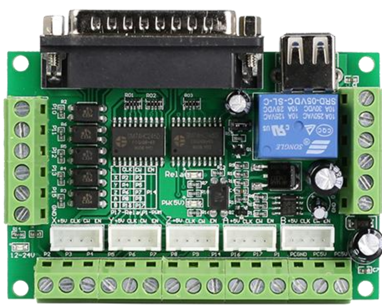
The ST-v2 Breakout Board, manufactured by StepperOnline (Part ID: ST-v2), is designed to simplify the connection and use of the STMicroelectronics ST-v2 microcontroller. This breakout board provides easy access to the microcontroller's pins and functionalities, making it an ideal choice for both prototyping and development purposes.
Explore Projects Built with ST-v2 Breakout board
Wi-Fi Controlled Environmental Monitoring System with Dual Stepper Motor Valve Actuation
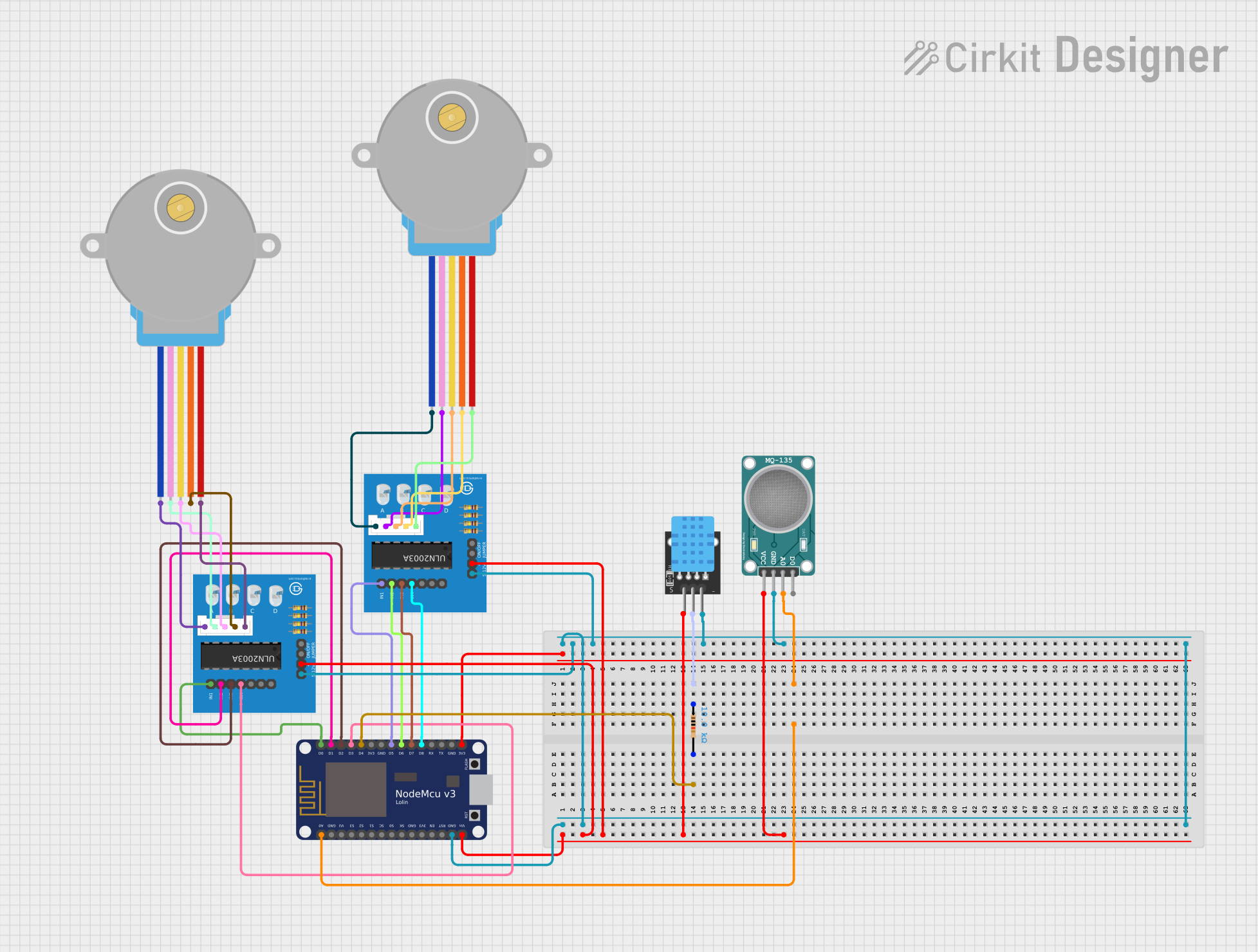
This circuit features two 28BYJ-48 stepper motors controlled by ULN2003A breakout boards, interfaced with a NodeMCU V3 ESP8266 microcontroller. The NodeMCU collects environmental data from a DHT11 temperature and humidity sensor and an MQ-135 air quality sensor. The microcontroller uses WiFi for connectivity and controls the stepper motors based on the sensor inputs, likely for regulating environmental conditions.
ESP8266 NodeMCU Controlled Environment Monitoring System with Stepper Motor and Sensors
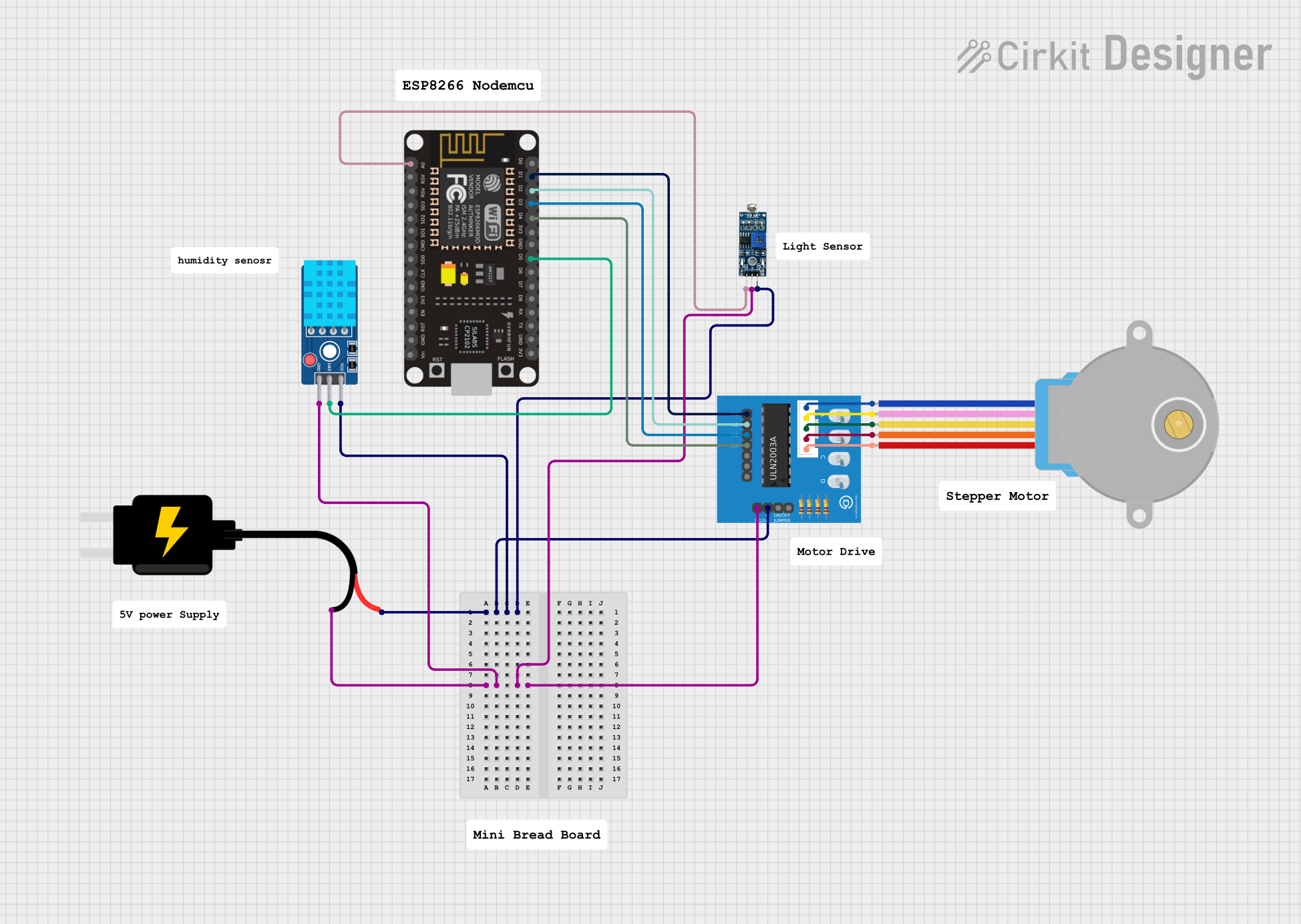
This circuit features an ESP8266 NodeMCU microcontroller connected to a ULN2003A breakout board to drive a 28BYJ-48 stepper motor. The ESP8266 also interfaces with a DHT11 temperature and humidity sensor and an LDR (light-dependent resistor) module for environmental sensing. Power is supplied by a 5V DC source, which is distributed to the motor driver, sensors, and the microcontroller.
Battery-Powered Arduino UNO and ESP-8266 Smart Controller with LCD and RTC

This circuit is a power management and control system that uses a 12V power supply and a 18650 Li-ion battery pack to provide a stable 5V output through a step-down buck converter. It includes an Arduino UNO, an ESP-8266 controller, a DS1307 RTC module, and a 20x4 I2C LCD display for monitoring and control purposes. The ULN2003A breakout board is used for driving higher current loads.
ESP32-Controlled Stepper Motors and Servo System
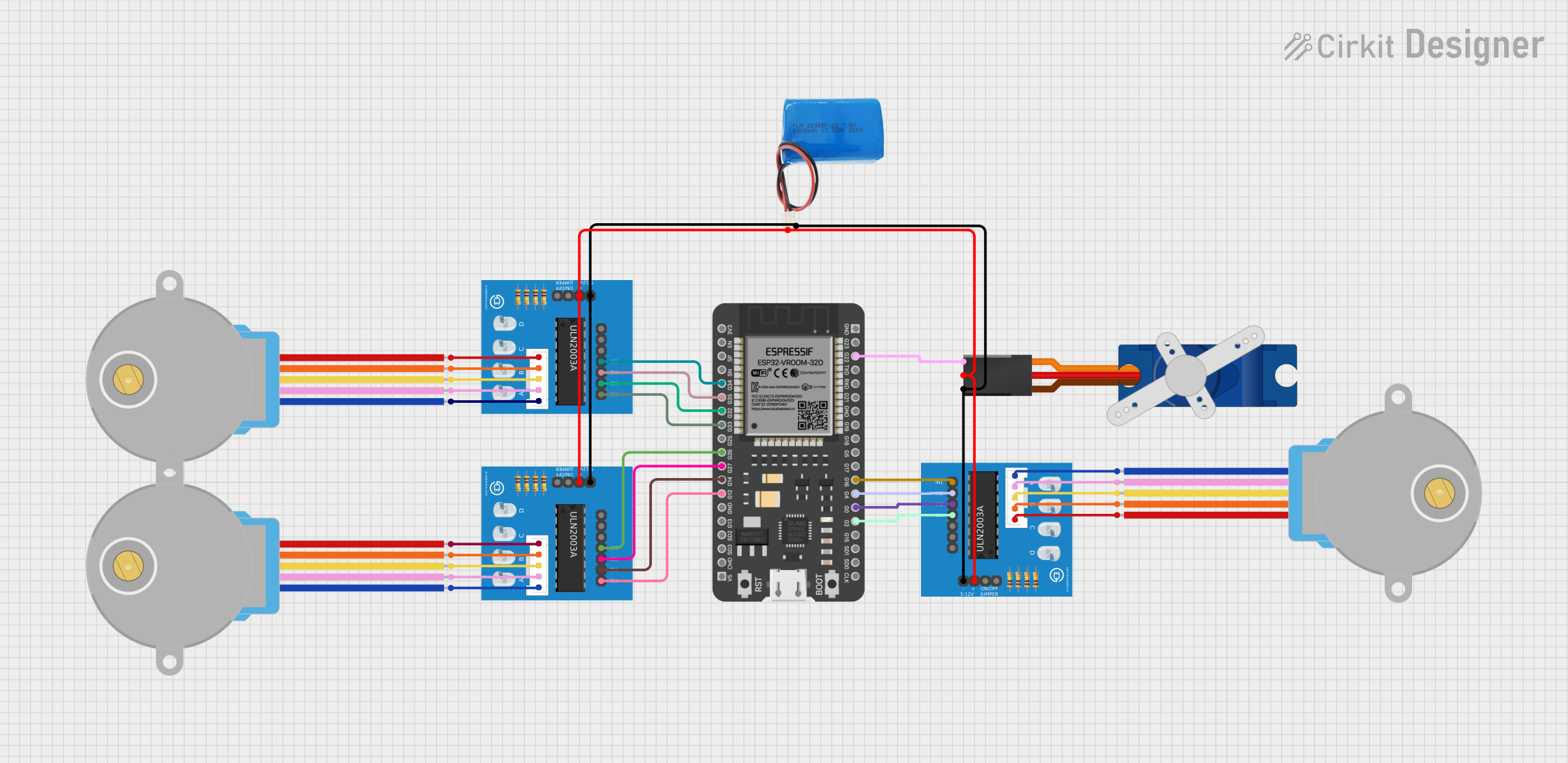
This circuit features an ESP32 microcontroller connected to three ULN2003A breakout boards, each of which is driving a 28BYJ-48 stepper motor. Additionally, there is a Tower Pro SG90 servo motor connected to the ESP32. The 5V battery provides power to the motors and the servo through the breakout boards, and the ESP32 controls the stepper motors and the servo motor via GPIO pins, enabling precise movement and positioning in applications such as robotics or automation systems.
Explore Projects Built with ST-v2 Breakout board
Wi-Fi Controlled Environmental Monitoring System with Dual Stepper Motor Valve Actuation
This circuit features two 28BYJ-48 stepper motors controlled by ULN2003A breakout boards, interfaced with a NodeMCU V3 ESP8266 microcontroller. The NodeMCU collects environmental data from a DHT11 temperature and humidity sensor and an MQ-135 air quality sensor. The microcontroller uses WiFi for connectivity and controls the stepper motors based on the sensor inputs, likely for regulating environmental conditions.
ESP8266 NodeMCU Controlled Environment Monitoring System with Stepper Motor and Sensors
This circuit features an ESP8266 NodeMCU microcontroller connected to a ULN2003A breakout board to drive a 28BYJ-48 stepper motor. The ESP8266 also interfaces with a DHT11 temperature and humidity sensor and an LDR (light-dependent resistor) module for environmental sensing. Power is supplied by a 5V DC source, which is distributed to the motor driver, sensors, and the microcontroller.
Battery-Powered Arduino UNO and ESP-8266 Smart Controller with LCD and RTC
This circuit is a power management and control system that uses a 12V power supply and a 18650 Li-ion battery pack to provide a stable 5V output through a step-down buck converter. It includes an Arduino UNO, an ESP-8266 controller, a DS1307 RTC module, and a 20x4 I2C LCD display for monitoring and control purposes. The ULN2003A breakout board is used for driving higher current loads.
ESP32-Controlled Stepper Motors and Servo System
This circuit features an ESP32 microcontroller connected to three ULN2003A breakout boards, each of which is driving a 28BYJ-48 stepper motor. Additionally, there is a Tower Pro SG90 servo motor connected to the ESP32. The 5V battery provides power to the motors and the servo through the breakout boards, and the ESP32 controls the stepper motors and the servo motor via GPIO pins, enabling precise movement and positioning in applications such as robotics or automation systems.
Common Applications and Use Cases
- Prototyping and Development: Ideal for rapid prototyping and development of embedded systems.
- Educational Projects: Suitable for educational purposes, helping students learn about microcontrollers and electronics.
- IoT Projects: Can be used in Internet of Things (IoT) projects for sensor interfacing and data collection.
- Robotics: Useful in robotics for motor control and sensor integration.
Technical Specifications
Key Technical Details
| Parameter | Value |
|---|---|
| Operating Voltage | 3.3V |
| Input Voltage | 5V (via USB) |
| Digital I/O Pins | 14 |
| Analog Input Pins | 6 |
| PWM Channels | 6 |
| Flash Memory | 32 KB |
| SRAM | 2 KB |
| Clock Speed | 16 MHz |
| Communication | UART, I2C, SPI |
Pin Configuration and Descriptions
| Pin Number | Pin Name | Description |
|---|---|---|
| 1 | VCC | 3.3V Power Supply |
| 2 | GND | Ground |
| 3 | D0 | Digital I/O Pin 0 |
| 4 | D1 | Digital I/O Pin 1 |
| 5 | D2 | Digital I/O Pin 2 |
| 6 | D3 | Digital I/O Pin 3 (PWM) |
| 7 | D4 | Digital I/O Pin 4 |
| 8 | D5 | Digital I/O Pin 5 (PWM) |
| 9 | D6 | Digital I/O Pin 6 (PWM) |
| 10 | D7 | Digital I/O Pin 7 |
| 11 | D8 | Digital I/O Pin 8 |
| 12 | D9 | Digital I/O Pin 9 (PWM) |
| 13 | D10 | Digital I/O Pin 10 (PWM) |
| 14 | D11 | Digital I/O Pin 11 (PWM) |
| 15 | A0 | Analog Input Pin 0 |
| 16 | A1 | Analog Input Pin 1 |
| 17 | A2 | Analog Input Pin 2 |
| 18 | A3 | Analog Input Pin 3 |
| 19 | A4 | Analog Input Pin 4 |
| 20 | A5 | Analog Input Pin 5 |
| 21 | RX | UART Receive |
| 22 | TX | UART Transmit |
| 23 | SCL | I2C Clock |
| 24 | SDA | I2C Data |
| 25 | MOSI | SPI Master Out Slave In |
| 26 | MISO | SPI Master In Slave Out |
| 27 | SCK | SPI Clock |
| 28 | RST | Reset |
Usage Instructions
How to Use the Component in a Circuit
- Power Supply: Connect the VCC pin to a 3.3V power source and the GND pin to ground.
- Digital I/O: Use the digital I/O pins (D0-D13) for interfacing with digital sensors, LEDs, and other components.
- Analog Inputs: Use the analog input pins (A0-A5) for reading analog sensors.
- Communication: Utilize the UART, I2C, and SPI pins for communication with other devices.
Important Considerations and Best Practices
- Voltage Levels: Ensure that the input voltage does not exceed 3.3V to avoid damaging the microcontroller.
- Pin Usage: Be mindful of the pin configuration and avoid conflicts when connecting multiple devices.
- Heat Dissipation: Ensure proper ventilation to prevent overheating during prolonged use.
Example Code for Arduino UNO
// Example code to blink an LED connected to pin D13

void setup() {
  pinMode(13, OUTPUT); // Set pin D13 as an output
}

void loop() {
  digitalWrite(13, HIGH); // Turn the LED on
  delay(1000);            // Wait for 1 second
  digitalWrite(13, LOW);  // Turn the LED off
  delay(1000);            // Wait for 1 second
}
Troubleshooting and FAQs
Common Issues Users Might Face
Microcontroller Not Powering On:
- Solution: Check the power supply connections and ensure that the VCC and GND pins are properly connected.
Digital Pins Not Responding:
- Solution: Verify the pin configuration in the code and ensure that the correct pins are being used.
Analog Readings Are Inaccurate:
- Solution: Ensure that the analog sensors are properly connected and that there is no electrical noise affecting the readings.
Communication Issues:
- Solution: Check the connections for UART, I2C, and SPI communication and ensure that the correct pins are being used.
Solutions and Tips for Troubleshooting
- Check Connections: Always double-check the connections to ensure that all pins are properly connected.
- Use a Multimeter: Use a multimeter to check the voltage levels and continuity of the connections.
- Consult the Datasheet: Refer to the STMicroelectronics ST-v2 microcontroller datasheet for detailed information on pin configurations and functionalities.
By following this documentation, users can effectively utilize the ST-v2 Breakout Board in their projects, ensuring proper connections and functionality.