How to Use 8-bit Programmable Counter: Examples, Pinouts, and Specs

Introduction
The MC14569B is an 8-bit programmable counter designed and manufactured by Motorola. It is a digital circuit component capable of counting in binary from 0 to 255. One of the key features of this counter is the ability to set the starting count value using programming signals, making it highly versatile for a range of applications. Common use cases include digital clocks, frequency dividers, timers, and event counters in embedded systems.
Explore Projects Built with 8-bit Programmable Counter
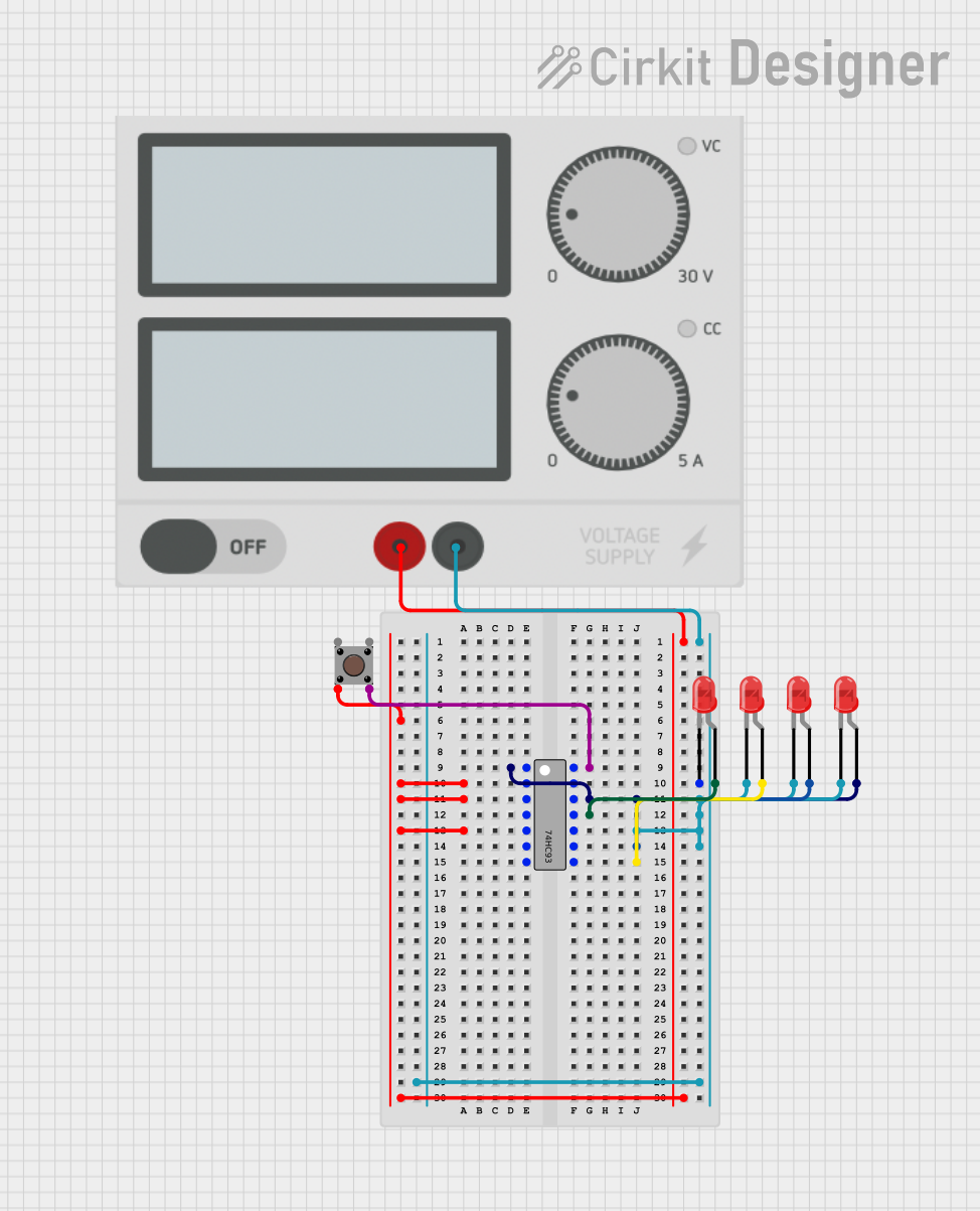
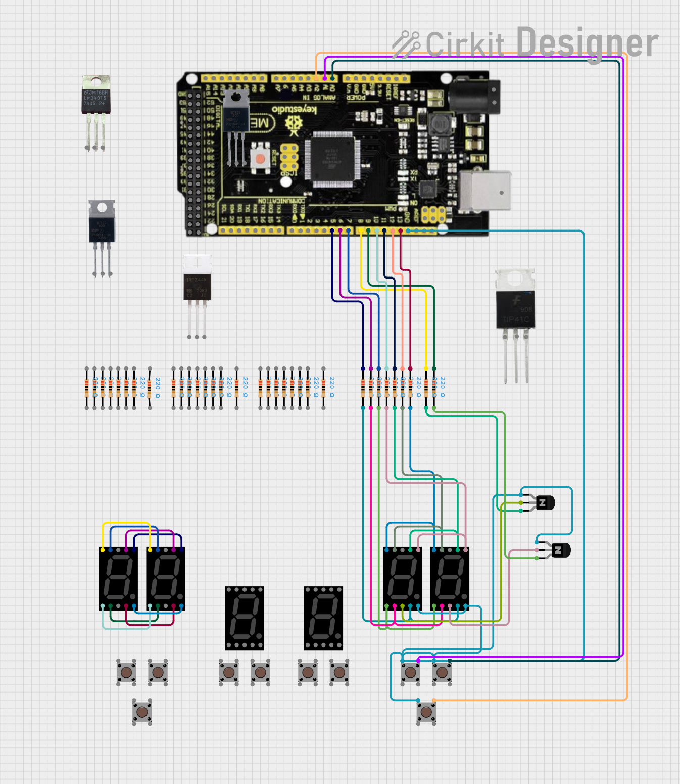
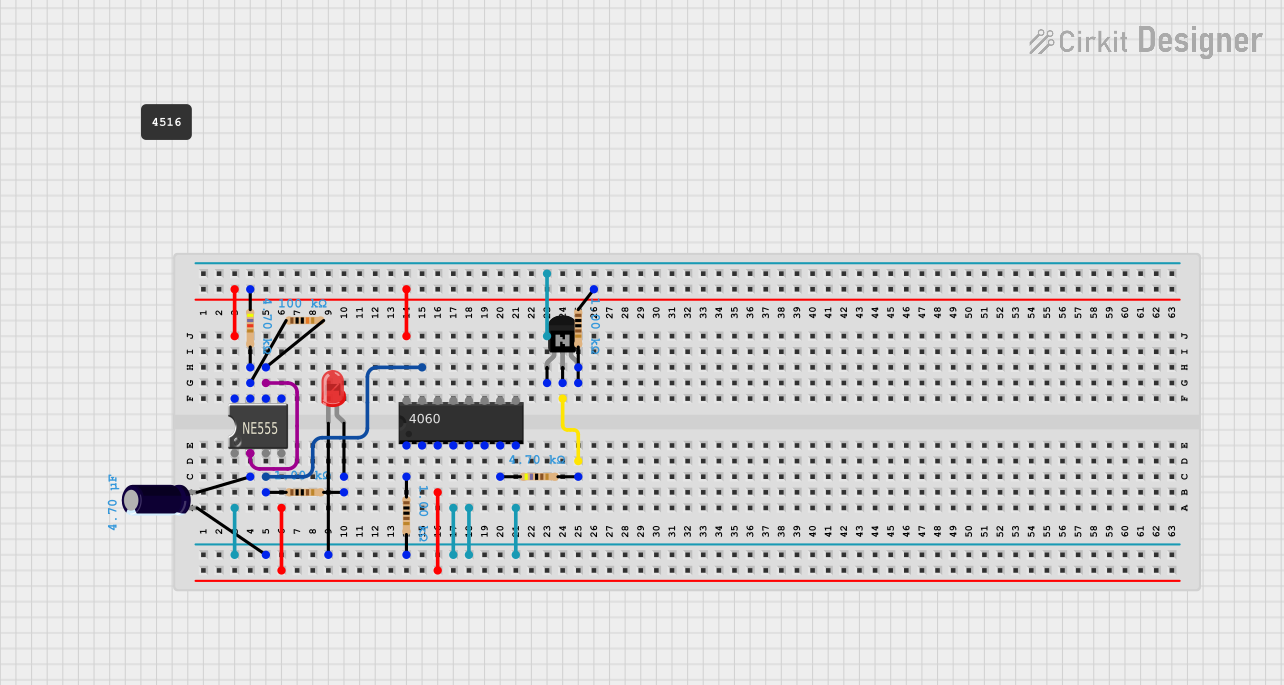
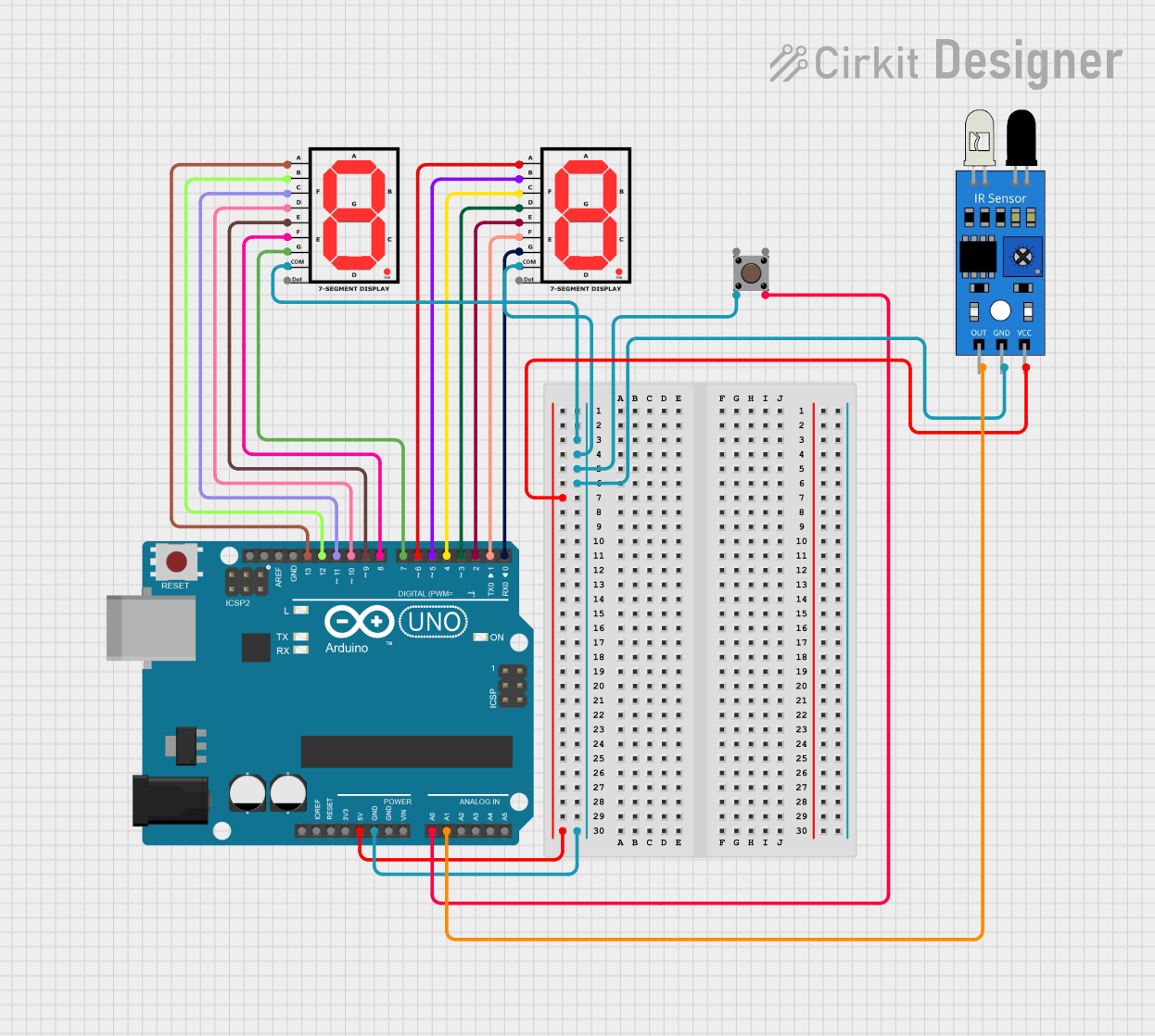
Explore Projects Built with 8-bit Programmable Counter
Technical Specifications
Key Technical Details
- Supply Voltage (Vcc): 3V to 18V
- Input Voltage (Vin): -1.5V to Vcc + 1.5V
- Output Voltage (Vout): -0.5V to Vcc + 0.5V
- Operating Temperature: -55°C to +125°C
- Count Range: 0 to 255 (8-bit binary)
- Package: 16-pin DIP (Dual In-line Package)
Pin Configuration and Descriptions
| Pin Number | Name | Description |
|---|---|---|
| 1 | Vss | Ground reference for the circuit. |
| 2 | Q0 | Least significant bit (LSB) of the counter output. |
| 3 | Q1 | Second least significant bit of the counter output. |
| 4 | Q2 | Third bit of the counter output. |
| 5 | Q3 | Fourth bit of the counter output. |
| 6 | Q4 | Fifth bit of the counter output. |
| 7 | Q5 | Sixth bit of the counter output. |
| 8 | Q6 | Seventh bit of the counter output. |
| 9 | Q7 | Most significant bit (MSB) of the counter output. |
| 10 | PE | Programming enable input. Active low. |
| 11 | DATA | Programming data input. |
| 12 | CLK | Clock input. Counter advances on the rising edge. |
| 13 | RESET | Resets the counter to the programmed value when low. |
| 14 | Vcc | Positive supply voltage input. |
Usage Instructions
How to Use the MC14569B in a Circuit
- Power Supply: Connect Vcc to a positive supply voltage within the specified range and Vss to the ground.
- Programming the Counter:
- To program the counter, pull the PE pin low.
- Apply the desired starting binary value to the Q0-Q7 pins, with Q0 being the LSB and Q7 the MSB.
- Once the desired value is set, release the PE pin to high to enable counting.
- Counting:
- Apply a low-to-high transition pulse to the CLK pin to increment the counter.
- The current count can be read from the Q0-Q7 output pins at any time.
- Resetting the Counter:
- To reset the counter to the programmed value, apply a low pulse to the RESET pin.
Important Considerations and Best Practices
- Ensure that the power supply does not exceed the maximum voltage rating to prevent damage to the component.
- Use a pull-up resistor on the PE pin to ensure it remains high during normal operation.
- Debounce the CLK input if mechanical switches are used to avoid erroneous counts.
- Utilize a proper decoupling capacitor close to the Vcc pin to minimize power supply noise.
Troubleshooting and FAQs
Common Issues
- Counter Not Incrementing: Verify that the CLK input is receiving clean transition pulses and that the PE pin is not held low.
- Incorrect Starting Value: Ensure that the programming sequence is correctly followed and that the DATA input is stable when the PE pin is released.
- No Output on Pins Q0-Q7: Check if the RESET pin is not held low and that the supply voltage is within the specified range.
Solutions and Tips for Troubleshooting
- If the counter is not responding as expected, double-check the connections and ensure that all inputs are within their specified voltage ranges.
- For erratic counting, consider adding a debounce circuit to the CLK input.
- Verify that the power supply is stable and that there is no excessive noise that could be affecting the counter's operation.
FAQs
Q: Can the MC14569B be used with an Arduino UNO? A: Yes, the MC14569B can be interfaced with an Arduino UNO for various projects requiring counting capabilities.
Q: What is the maximum frequency the MC14569B can count? A: The maximum frequency depends on the supply voltage. Refer to the manufacturer's datasheet for detailed timing specifications.
Q: How can I reset the counter to zero? A: The MC14569B does not reset to zero but to the programmed starting value. To reset to zero, program the counter with all outputs (Q0-Q7) set to low.
Example Arduino UNO Code
// Define the pins connected to the counter
const int clockPin = 2; // CLK pin connected to digital pin 2
const int resetPin = 3; // RESET pin connected to digital pin 3

void setup() {
  pinMode(clockPin, OUTPUT);
  pinMode(resetPin, OUTPUT);

  // Reset the counter at the start
  digitalWrite(resetPin, LOW);
  delay(10); // Wait for 10 milliseconds
  digitalWrite(resetPin, HIGH);
}

void loop() {
  // Increment the counter
  digitalWrite(clockPin, HIGH);
  delay(10); // Wait for 10 milliseconds
  digitalWrite(clockPin, LOW);
  delay(1000); // Wait for 1 second between counts
}
Note: This code assumes that the MC14569B has been programmed with a starting value prior to being used with the Arduino. The code provided simply increments the counter every second and resets the counter at the beginning of the program.