How to Use Peltier Module: Examples, Pinouts, and Specs
Introduction
A Peltier module, also known as a thermoelectric cooler (TEC), is a semiconductor-based electronic component that operates on the Peltier effect. It is capable of transferring heat from one side of the device to the other with the passage of electric current, resulting in a temperature differential. This unique property allows the Peltier module to either heat or cool an object or space, depending on the direction of the current. Common applications include electronic cooling systems, portable refrigerators, temperature control for optical devices, and even in experimental setups requiring precise temperature regulation.
Explore Projects Built with Peltier Module
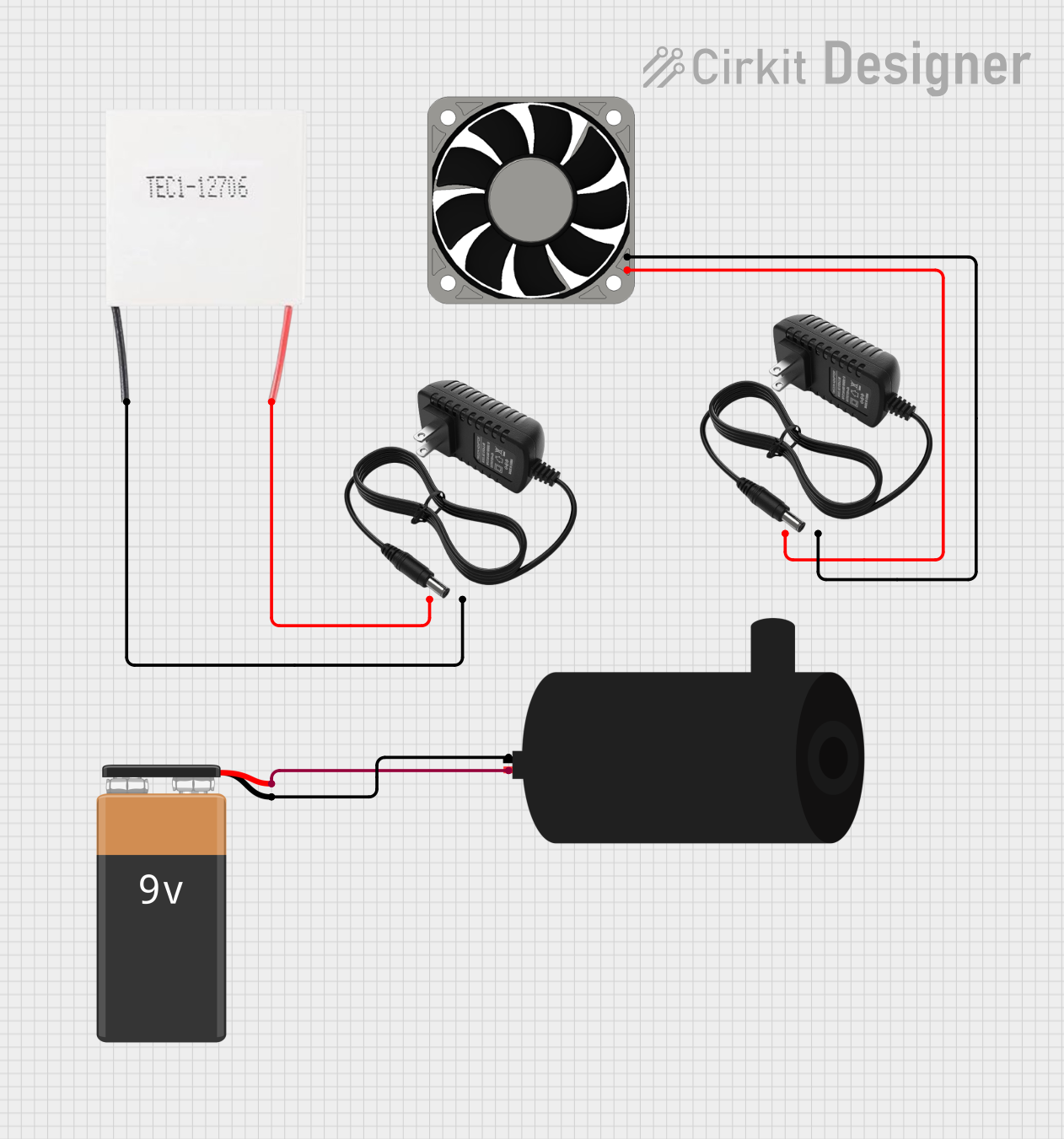

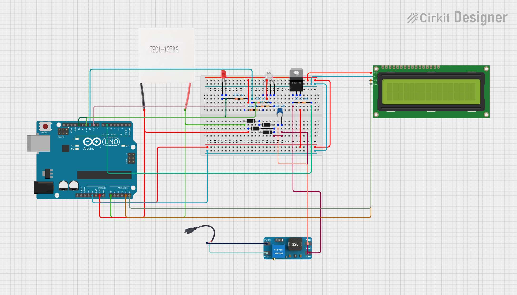
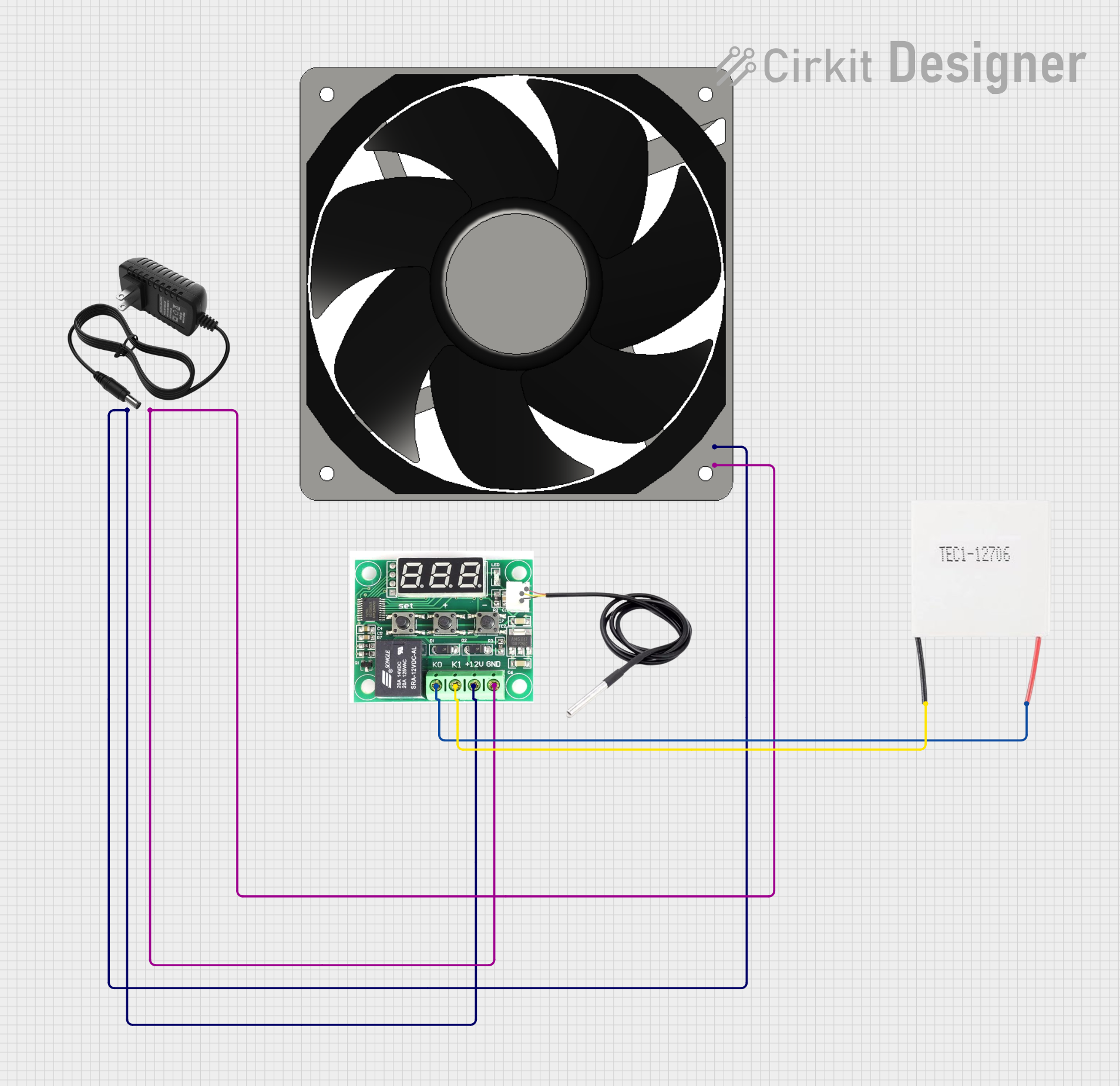
Explore Projects Built with Peltier Module
Technical Specifications
Key Technical Details
- Operating Voltage Range: Typically 3.0V to 15.0V
- Maximum Current: Depends on the model (e.g., 5A, 6A)
- Maximum Power Consumption: Varies with model and operating conditions
- Temperature Differential (ΔTmax): Up to 70°C under optimal conditions
- Operating Temperature Range: -30°C to 70°C
- Dimensions: Varies with model (e.g., 40mm x 40mm x 3.6mm)
Pin Configuration and Descriptions
| Pin Number | Description |
|---|---|
| 1 | Positive Voltage (V+) |
| 2 | Negative Voltage (V-) |
Usage Instructions
Integration into a Circuit
To use a Peltier module in a circuit:
- Identify the hot and cold sides of the module.
- Connect the positive terminal of the power supply to the positive (V+) pin of the Peltier module.
- Connect the negative terminal of the power supply to the negative (V-) pin of the Peltier module.
- Apply the appropriate voltage as per the module's specifications.
Important Considerations and Best Practices
- Heat Sinking: The hot side of the Peltier module must be adequately heat-sinked to prevent overheating and ensure efficient operation.
- Power Supply: Use a stable and regulated power supply to avoid damaging the module.
- Current Limiting: Ensure that the current does not exceed the maximum rating of the Peltier module.
- Thermal Compound: Apply thermal compound between the module and the heat sinks to improve heat transfer.
- Insulation: Properly insulate the module to prevent condensation when cooling below the dew point.
Troubleshooting and FAQs
Common Issues
- Insufficient Cooling/Heating: This could be due to inadequate heat sinking, insufficient power supply, or incorrect assembly.
- Module Overheating: Overheating can occur if the hot side is not properly heat-sinked or if the module is driven beyond its rated current.
- Short Lifespan: Operating the module at extreme temperatures or voltages can reduce its lifespan.
Solutions and Tips
- Ensure proper heat sinking: Always use a heat sink on the hot side and consider a fan for active cooling.
- Check power supply: Verify that the power supply is within the module's operating range and is stable.
- Review assembly: Make sure the module is assembled correctly with thermal compound and insulation as needed.
FAQs
Q: Can I reverse the heating and cooling sides? A: Yes, reversing the polarity of the power supply will switch the hot and cold sides.
Q: How do I control the temperature with a Peltier module? A: You can control the temperature by adjusting the voltage or using a pulse-width modulation (PWM) signal to regulate the power.
Q: Is it possible to stack Peltier modules for greater temperature differential? A: While it is possible, it requires careful consideration of the power supply and heat sinking to prevent damage.
Example Arduino UNO Code
Below is an example code snippet for controlling a Peltier module with an Arduino UNO using PWM:
int peltierPin = 3; // Connect Peltier module to pin 3 (PWM capable)

void setup() {
  pinMode(peltierPin, OUTPUT);
}

void loop() {
  // Set PWM for Peltier module (0 (off) to 255 (max power))
  analogWrite(peltierPin, 127); // 50% power

  // Note: To reverse the heating/cooling effect, you can use a H-bridge.

  // Add your code to control the temperature as needed.
}
Remember to use a suitable driver or a relay when connecting the Peltier module to the Arduino, as the module may require more current than the Arduino can directly supply.