Cirkit Designer Logo
Cirkit Designer
Your all-in-one circuit design IDE
Home / 
Component Documentation

How to Use ACS758: Examples, Pinouts, and Specs

Image of ACS758
Cirkit Designer LogoDesign with ACS758 in Cirkit Designer

Introduction

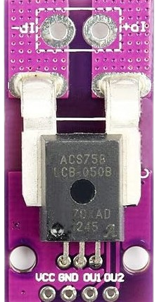
The ACS758 is a Hall-effect-based current sensor designed for accurate and isolated current measurement. It is capable of measuring both AC and DC currents, making it a versatile component for a wide range of applications. The sensor outputs an analog voltage proportional to the current flowing through its primary conductor, enabling real-time monitoring and control.

Explore Projects Built with ACS758

Use Cirkit Designer to design, explore, and prototype these projects online. Some projects support real-time simulation. Click "Open Project" to start designing instantly!
Satellite-Based Timing and Navigation System with SDR and Atomic Clock Synchronization
Image of GPS 시스템 측정 구성도_Confirm: A project utilizing ACS758 in a practical application
This circuit appears to be a complex system involving power supply management, GPS and timing synchronization, and data communication. It includes a SI-TEX G1 Satellite Compass for GPS data, an XHTF1021 Atomic Rubidium Clock for precise timing, and Ettus USRP B200 units for software-defined radio communication. Power is supplied through various SMPS units and distributed via terminal blocks and DC jacks. Data communication is facilitated by Beelink MINI S12 N95 computers, RS232 splitters, and a 1000BASE-T Media Converter for network connectivity. RF Directional Couplers are used to interface antennas with the USRP units, and the entire system is likely contained within cases for protection and organization.
Cirkit Designer LogoOpen Project in Cirkit Designer
Battery-Powered Emergency Alert System with NUCLEO-F072RB, SIM800L, and GPS NEO 6M
Image of women safety: A project utilizing ACS758 in a practical application
This circuit is an emergency alert system that uses a NUCLEO-F072RB microcontroller to send SMS alerts and make calls via a SIM800L GSM module, while obtaining location data from a GPS NEO 6M module. The system is powered by a Li-ion battery and includes a TP4056 module for battery charging and protection, with a rocker switch to control power to the microcontroller.
Cirkit Designer LogoOpen Project in Cirkit Designer
Arduino Nano Based GPS Tracker with GSM Communication and Accelerometer
Image of Circuit Aayush: A project utilizing ACS758 in a practical application
This circuit is designed for communication and location tracking purposes. It features an Arduino Nano interfaced with a SIM800L GSM module for cellular connectivity, a GPS NEO 6M module for obtaining geographical coordinates, and an AITrip ADXL335 GY-61 accelerometer for motion sensing. The LM2596 Step Down Module is used to regulate the power supply to the components.
Cirkit Designer LogoOpen Project in Cirkit Designer
Raspberry Pi and H743-SLIM V3 Controlled Servo System with GPS and Telemetry
Image of Avionics Wiring Diagram: A project utilizing ACS758 in a practical application
This circuit is designed for a UAV control system, featuring an H743-SLIM V3 flight controller connected to multiple servos for control surfaces, a GPS module for navigation, a telemetry radio for communication, and a digital airspeed sensor for flight data. The system is powered by a LiPo battery and includes a Raspberry Pi for additional processing and control tasks.
Cirkit Designer LogoOpen Project in Cirkit Designer

Explore Projects Built with ACS758

Use Cirkit Designer to design, explore, and prototype these projects online. Some projects support real-time simulation. Click "Open Project" to start designing instantly!
Image of GPS 시스템 측정 구성도_Confirm: A project utilizing ACS758 in a practical application
Satellite-Based Timing and Navigation System with SDR and Atomic Clock Synchronization
This circuit appears to be a complex system involving power supply management, GPS and timing synchronization, and data communication. It includes a SI-TEX G1 Satellite Compass for GPS data, an XHTF1021 Atomic Rubidium Clock for precise timing, and Ettus USRP B200 units for software-defined radio communication. Power is supplied through various SMPS units and distributed via terminal blocks and DC jacks. Data communication is facilitated by Beelink MINI S12 N95 computers, RS232 splitters, and a 1000BASE-T Media Converter for network connectivity. RF Directional Couplers are used to interface antennas with the USRP units, and the entire system is likely contained within cases for protection and organization.
Cirkit Designer LogoOpen Project in Cirkit Designer
Image of women safety: A project utilizing ACS758 in a practical application
Battery-Powered Emergency Alert System with NUCLEO-F072RB, SIM800L, and GPS NEO 6M
This circuit is an emergency alert system that uses a NUCLEO-F072RB microcontroller to send SMS alerts and make calls via a SIM800L GSM module, while obtaining location data from a GPS NEO 6M module. The system is powered by a Li-ion battery and includes a TP4056 module for battery charging and protection, with a rocker switch to control power to the microcontroller.
Cirkit Designer LogoOpen Project in Cirkit Designer
Image of Circuit Aayush: A project utilizing ACS758 in a practical application
Arduino Nano Based GPS Tracker with GSM Communication and Accelerometer
This circuit is designed for communication and location tracking purposes. It features an Arduino Nano interfaced with a SIM800L GSM module for cellular connectivity, a GPS NEO 6M module for obtaining geographical coordinates, and an AITrip ADXL335 GY-61 accelerometer for motion sensing. The LM2596 Step Down Module is used to regulate the power supply to the components.
Cirkit Designer LogoOpen Project in Cirkit Designer
Image of Avionics Wiring Diagram: A project utilizing ACS758 in a practical application
Raspberry Pi and H743-SLIM V3 Controlled Servo System with GPS and Telemetry
This circuit is designed for a UAV control system, featuring an H743-SLIM V3 flight controller connected to multiple servos for control surfaces, a GPS module for navigation, a telemetry radio for communication, and a digital airspeed sensor for flight data. The system is powered by a LiPo battery and includes a Raspberry Pi for additional processing and control tasks.
Cirkit Designer LogoOpen Project in Cirkit Designer

Common Applications and Use Cases

  • Power monitoring in industrial and consumer electronics
  • Battery management systems (BMS)
  • Motor control and protection
  • Solar inverters and renewable energy systems
  • Overcurrent protection in power supplies

Technical Specifications

The ACS758 is available in various models with different current ranges. Below are the key technical details:

Parameter Value
Supply Voltage (Vcc) 3.0V to 5.5V
Current Measurement Range ±50A, ±100A, ±150A, ±200A (model-dependent)
Sensitivity 20mV/A to 40mV/A (model-dependent)
Output Voltage Range 0.5V to 4.5V (nominal)
Bandwidth 120 kHz
Response Time 4 µs
Isolation Voltage 3.0 kV RMS
Operating Temperature Range -40°C to +150°C

Pin Configuration and Descriptions

The ACS758 is typically available in a 5-pin package. Below is the pinout description:

Pin Number Pin Name Description
1 Vcc Power supply input (3.0V to 5.5V)
2 GND Ground connection
3 VIOUT Analog output voltage proportional to current
4 IP+ Positive current input terminal
5 IP- Negative current input terminal

Usage Instructions

How to Use the ACS758 in a Circuit

  1. Power Supply: Connect the Vcc pin to a stable 3.3V or 5V power supply and the GND pin to the ground of the circuit.
  2. Current Path: Pass the current to be measured through the IP+ and IP- terminals. Ensure the current does not exceed the sensor's rated range.
  3. Output Signal: Connect the VIOUT pin to an analog input of a microcontroller or an ADC (Analog-to-Digital Converter) to read the voltage output.
  4. Calibration: The output voltage at zero current is typically 2.5V (for a 5V supply). Use this as a reference point for calibration.

Important Considerations and Best Practices

  • Electrical Isolation: The ACS758 provides galvanic isolation between the current-carrying conductor and the output signal, ensuring safety in high-voltage applications.
  • Filtering: Add a decoupling capacitor (e.g., 0.1 µF) between Vcc and GND to reduce noise.
  • Orientation: Ensure the current flows in the correct direction through the IP+ and IP- terminals to avoid incorrect readings.
  • Temperature Compensation: The sensor's output may vary slightly with temperature. Consider implementing software compensation if precise measurements are required.

Example: Using ACS758 with Arduino UNO

Below is an example of how to interface the ACS758 with an Arduino UNO to measure current:

// Define the analog pin connected to the ACS758 VIOUT pin
const int sensorPin = A0;

// Define the zero-current output voltage (2.5V for 5V supply)
const float zeroCurrentVoltage = 2.5;

// Define the sensitivity of the ACS758 (e.g., 40mV/A for ±50A model)
const float sensitivity = 0.04; // 40mV/A

void setup() {
  Serial.begin(9600); // Initialize serial communication
}

void loop() {
  // Read the analog value from the sensor
  int sensorValue = analogRead(sensorPin);

  // Convert the analog value to voltage (assuming 5V reference)
  float voltage = sensorValue * (5.0 / 1023.0);

  // Calculate the current in Amperes
  float current = (voltage - zeroCurrentVoltage) / sensitivity;

  // Print the current to the Serial Monitor
  Serial.print("Current: ");
  Serial.print(current);
  Serial.println(" A");

  delay(1000); // Wait for 1 second before the next reading
}

Troubleshooting and FAQs

Common Issues and Solutions

  1. No Output or Incorrect Readings:

    • Ensure the Vcc and GND pins are properly connected to a stable power supply.
    • Verify that the current through the IP+ and IP- terminals is within the sensor's rated range.
    • Check for loose or incorrect wiring.
  2. Noisy Output Signal:

    • Add a decoupling capacitor (e.g., 0.1 µF) between Vcc and GND to filter noise.
    • Use shielded cables for the current-carrying conductor to reduce electromagnetic interference.
  3. Output Voltage Does Not Match Expected Value:

    • Verify the sensitivity value for your specific ACS758 model.
    • Ensure the zero-current output voltage (typically 2.5V) is correctly accounted for in calculations.
  4. Temperature-Related Drift:

    • Use software compensation to account for temperature variations if precise measurements are required.

FAQs

Q: Can the ACS758 measure both AC and DC currents?
A: Yes, the ACS758 can measure both AC and DC currents accurately.

Q: What happens if the current exceeds the sensor's rated range?
A: Exceeding the rated current may damage the sensor or result in inaccurate readings. Always choose a model with an appropriate current range for your application.

Q: Is the ACS758 suitable for high-voltage applications?
A: Yes, the ACS758 provides electrical isolation up to 3.0 kV RMS, making it suitable for high-voltage applications.

Q: How do I select the correct ACS758 model for my application?
A: Choose a model with a current range that matches or slightly exceeds the maximum current in your application. For example, use the ±50A model for currents up to 50A.

Q: Can I use the ACS758 with a 3.3V microcontroller?
A: Yes, the ACS758 operates with a supply voltage as low as 3.0V, making it compatible with 3.3V systems.