How to Use IIoT Development Kit B: Examples, Pinouts, and Specs
Introduction
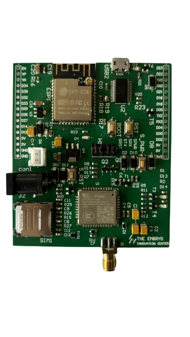
The IIoT Development Kit B by SLT is a comprehensive toolkit designed to accelerate the development of Industrial Internet of Things (IIoT) applications. This kit integrates a variety of sensors, connectivity modules, and development tools, enabling rapid prototyping and deployment of IIoT solutions. It is ideal for industrial automation, predictive maintenance, smart manufacturing, and other IIoT use cases.
Explore Projects Built with IIoT Development Kit B
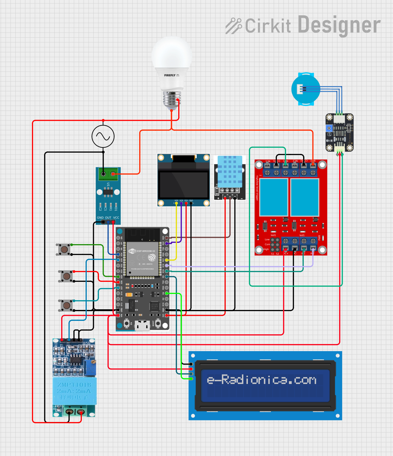
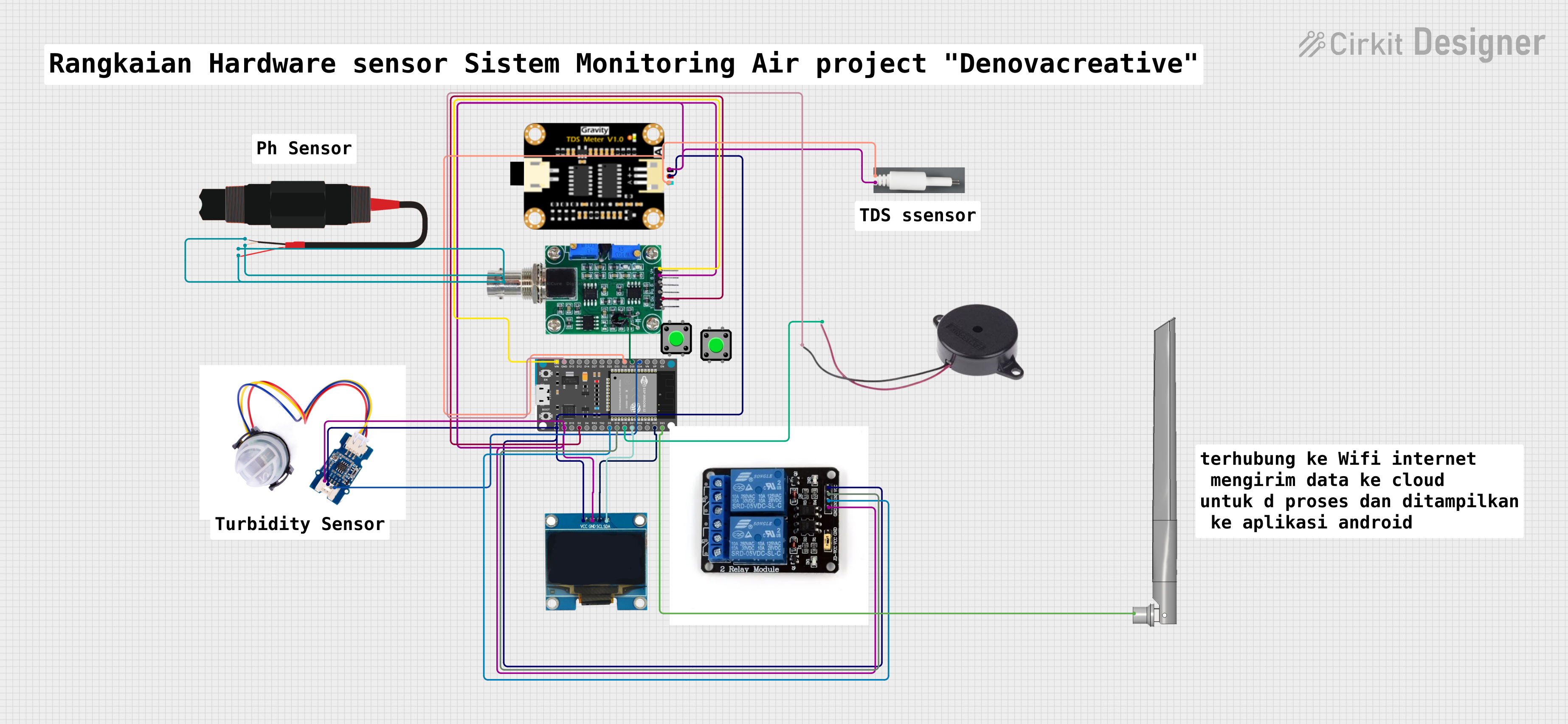


Explore Projects Built with IIoT Development Kit B
Common Applications and Use Cases
- Industrial Automation: Monitor and control industrial processes in real-time.
- Predictive Maintenance: Collect sensor data to predict equipment failures.
- Smart Manufacturing: Enable data-driven decision-making in production lines.
- Environmental Monitoring: Track temperature, humidity, and other environmental parameters.
- Asset Tracking: Monitor the location and status of industrial assets.
Technical Specifications
Key Technical Details
| Parameter | Specification |
|---|---|
| Microcontroller | ARM Cortex-M4, 32-bit, 120 MHz |
| Connectivity Options | Wi-Fi, Bluetooth 5.0, Ethernet, LoRaWAN |
| Sensors Included | Temperature, Humidity, Accelerometer, Gyroscope |
| Operating Voltage | 3.3V - 5V |
| Power Supply | USB-C (5V, 2A) or external DC input (7V - 12V) |
| GPIO Pins | 20 (Digital and Analog) |
| Communication Protocols | UART, SPI, I2C, CAN, Modbus |
| Storage | 16 MB Flash, MicroSD card slot (up to 32 GB) |
| Dimensions | 100 mm x 70 mm x 20 mm |
| Operating Temperature | -20°C to 85°C |
Pin Configuration and Descriptions
| Pin Number | Pin Name | Description |
|---|---|---|
| 1 | GND | Ground |
| 2 | VCC | Power input (3.3V - 5V) |
| 3 | GPIO1 | General-purpose I/O pin |
| 4 | GPIO2 | General-purpose I/O pin |
| 5 | SDA | I2C Data Line |
| 6 | SCL | I2C Clock Line |
| 7 | TX | UART Transmit |
| 8 | RX | UART Receive |
| 9 | SPI_MOSI | SPI Master Out Slave In |
| 10 | SPI_MISO | SPI Master In Slave Out |
| 11 | SPI_SCK | SPI Clock |
| 12 | CAN_H | CAN Bus High |
| 13 | CAN_L | CAN Bus Low |
| 14 | ADC1 | Analog-to-Digital Converter Input 1 |
| 15 | ADC2 | Analog-to-Digital Converter Input 2 |
| 16 | PWM1 | Pulse Width Modulation Output 1 |
| 17 | PWM2 | Pulse Width Modulation Output 2 |
| 18 | ETH_TX | Ethernet Transmit |
| 19 | ETH_RX | Ethernet Receive |
| 20 | RESET | Reset Pin |
Usage Instructions
How to Use the Component in a Circuit
- Powering the Kit: Connect the kit to a 5V USB-C power source or an external DC power supply (7V - 12V).
- Connecting Sensors: Use the GPIO pins or dedicated I2C/SPI/UART interfaces to connect additional sensors or actuators.
- Programming: Use the USB-C port to connect the kit to a computer for programming. The kit is compatible with popular IDEs such as Arduino IDE, PlatformIO, and SLT's proprietary development environment.
- Networking: Configure the desired connectivity option (Wi-Fi, Bluetooth, Ethernet, or LoRaWAN) using the provided libraries and example code.
Important Considerations and Best Practices
- Power Supply: Ensure the power supply meets the voltage and current requirements to avoid damage.
- Pin Usage: Avoid exceeding the maximum current rating of GPIO pins (20 mA per pin).
- Firmware Updates: Regularly update the firmware to access the latest features and security patches.
- Environmental Conditions: Operate the kit within the specified temperature range (-20°C to 85°C).
Example Code for Arduino UNO
Below is an example of how to read temperature and humidity data from the onboard sensor and send it via UART:
#include <Wire.h>
#include <DHT.h>

// Define the DHT sensor type and pin
#define DHTPIN 3       // GPIO3 is connected to the DHT sensor
#define DHTTYPE DHT22  // DHT22 sensor type

DHT dht(DHTPIN, DHTTYPE);

void setup() {
  Serial.begin(9600);  // Initialize UART communication
  dht.begin();         // Initialize the DHT sensor
  Serial.println("IIoT Development Kit B - Sensor Test");
}

void loop() {
  // Read temperature and humidity from the DHT sensor
  float temperature = dht.readTemperature();
  float humidity = dht.readHumidity();

  // Check if the readings are valid
  if (isnan(temperature) || isnan(humidity)) {
    Serial.println("Failed to read from DHT sensor!");
    return;
  }

  // Print the sensor data to the Serial Monitor
  Serial.print("Temperature: ");
  Serial.print(temperature);
  Serial.println(" °C");

  Serial.print("Humidity: ");
  Serial.print(humidity);
  Serial.println(" %");

  delay(2000);  // Wait for 2 seconds before the next reading
}
Troubleshooting and FAQs
Common Issues and Solutions
The kit does not power on:
- Ensure the power supply is connected properly and meets the voltage/current requirements.
- Check the USB-C cable or external DC adapter for faults.
Sensors are not providing data:
- Verify the sensor connections to the appropriate GPIO or communication pins.
- Ensure the correct libraries are installed and included in your code.
Connectivity issues (Wi-Fi/Bluetooth/Ethernet):
- Double-check the network credentials and configuration settings in your code.
- Ensure the antenna (if external) is securely connected.
Microcontroller not detected by the computer:
- Confirm the USB-C cable supports data transfer (not just charging).
- Install the necessary drivers for the development kit.
FAQs
Q: Can I use this kit with Raspberry Pi?
A: Yes, the kit can interface with Raspberry Pi via GPIO, I2C, SPI, or UART.Q: Is the kit compatible with cloud platforms?
A: Yes, the kit supports integration with popular cloud platforms like AWS IoT, Azure IoT, and Google Cloud IoT.Q: Can I add external sensors?
A: Absolutely! The kit provides multiple GPIO and communication interfaces for connecting additional sensors.Q: How do I update the firmware?
A: Use the SLT development environment or the provided firmware update tool to flash the latest firmware.
This documentation provides a comprehensive guide to using the IIoT Development Kit B effectively. For further assistance, refer to the official SLT support resources.