How to Use KeyeStudio Uno Prototype PCB: Examples, Pinouts, and Specs
Introduction
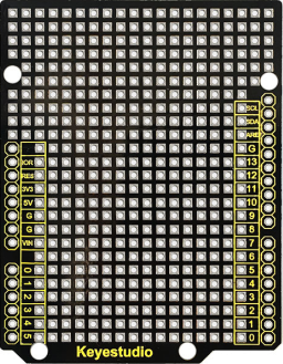
The KeyeStudio Uno Prototype PCB is a versatile and user-friendly platform designed for hobbyists, educators, and prototyping professionals. This prototyping printed circuit board is specifically tailored to be compatible with Arduino Uno boards, facilitating the easy connection and soldering of various electronic components. It is an essential tool for developing and testing new circuits before finalizing a design for production.
Explore Projects Built with KeyeStudio Uno Prototype PCB
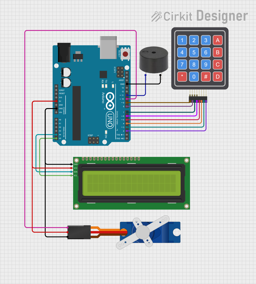
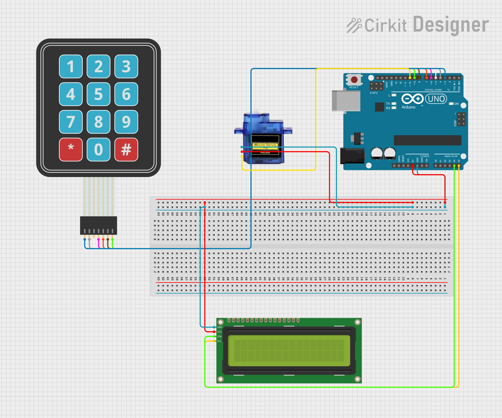
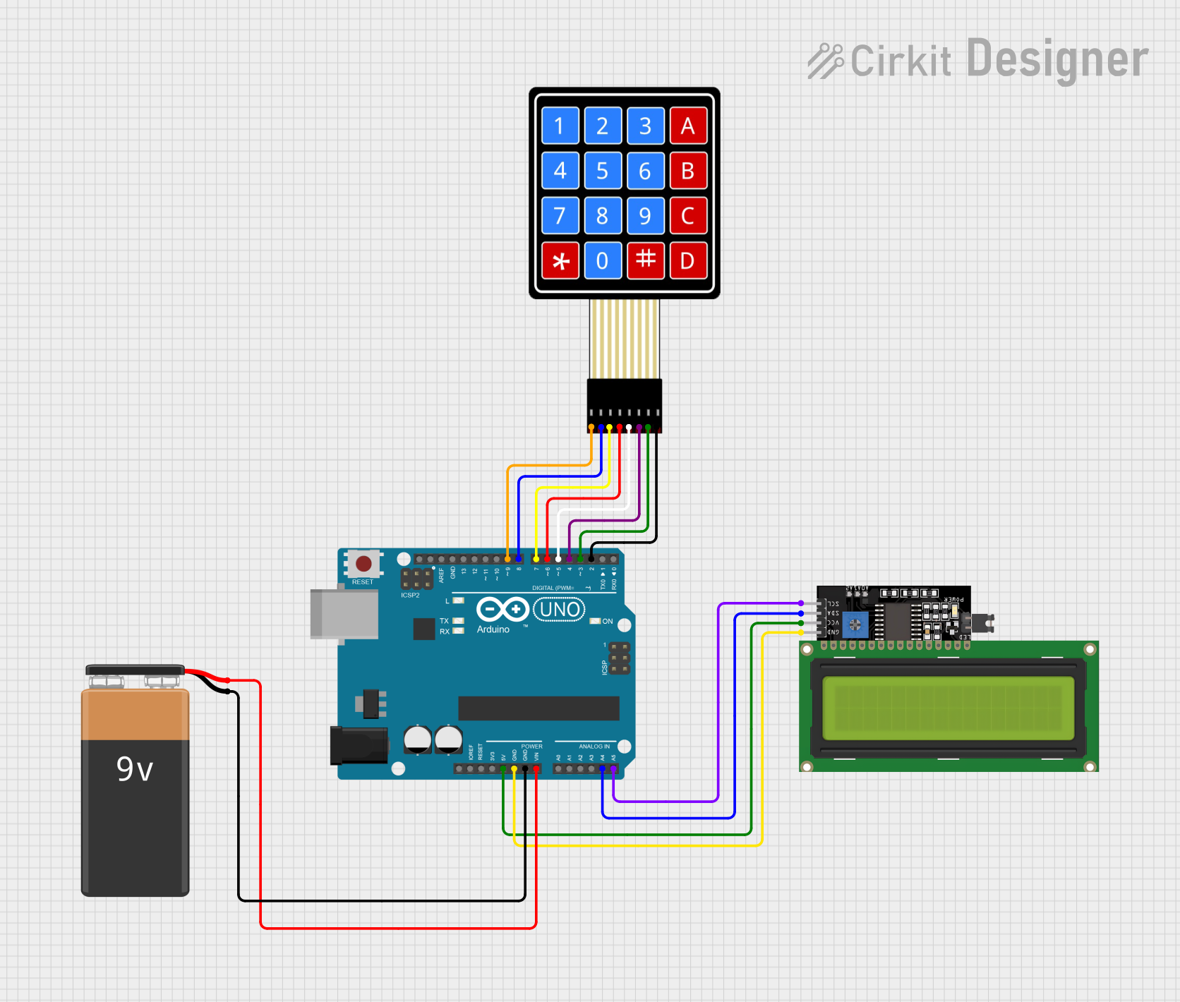
Explore Projects Built with KeyeStudio Uno Prototype PCB
Common Applications and Use Cases
- Rapid prototyping of electronic circuits
- Educational projects for learning electronics and programming
- Testing and debugging Arduino-based designs
- Creating custom shields for Arduino Uno
Technical Specifications
Key Technical Details
- Compatibility: Designed to interface directly with Arduino Uno
- Material: High-quality FR-4 glass fiber PCB
- Dimensions: Matches the Arduino Uno footprint
- Hole Pitch: Standard 2.54mm (0.1 inch) grid for DIP (Dual In-line Package) components
- Voltage and Current Ratings: Dependent on the components used on the board
Pin Configuration and Descriptions
| Pin Number | Description | Notes |
|---|---|---|
| 1-14 | Digital Pins (0-13) | Directly connected to Arduino |
| A0-A5 | Analog Input Pins | Directly connected to Arduino |
| GND | Ground Pins | Multiple for easy access |
| 5V | 5V Power Rail | Supplied by Arduino when connected |
| 3.3V | 3.3V Power Rail | Supplied by Arduino when connected |
| VIN | Voltage Input for Arduino | Can be used to power Arduino |
| RESET | Reset Pin | Connected to Arduino's reset |
Usage Instructions
How to Use the Component in a Circuit
- Aligning the Board: Align the KeyeStudio Uno Prototype PCB with the headers on the Arduino Uno.
- Soldering Components: Insert your electronic components into the provided holes, ensuring correct orientation and alignment with the grid.
- Connecting to Arduino: Use jumper wires or solder connections to make electrical connections between the components and the Arduino Uno pins.
- Powering the Circuit: Power can be supplied through the Arduino Uno when connected or through external sources connected to the VIN pin if required.
Important Considerations and Best Practices
- Soldering: Ensure good solder joints by heating the pad and the component lead simultaneously and applying solder. Avoid cold solder joints.
- Component Placement: Plan the layout of your components to minimize crossing wires and to allow for easy changes or debugging.
- Power Ratings: Be mindful of the power ratings of the components you are using to avoid damage to the PCB or the Arduino Uno.
- Testing: Before applying power, double-check all connections with a multimeter to ensure there are no shorts or incorrect connections.
Troubleshooting and FAQs
Common Issues Users Might Face
- Loose Connections: Ensure all components and wires are soldered properly.
- Short Circuits: Use a multimeter to check for shorts before powering the board.
- Component Failure: If a component is not working, check for correct orientation and soldering.
Solutions and Tips for Troubleshooting
- Visual Inspection: Look for any obvious signs of damage or incorrect soldering.
- Continuity Testing: Use a multimeter to check the continuity of connections.
- Isolate Circuits: Test sections of your circuit independently to isolate the issue.
FAQs
Q: Can I use the KeyeStudio Uno Prototype PCB with other Arduino models? A: The PCB is designed for the Arduino Uno form factor. It may not align with other models.
Q: How many components can the PCB accommodate? A: The number of components depends on their size and the complexity of the circuit. Plan your layout accordingly.
Q: Is it possible to reuse the PCB after desoldering components? A: Yes, with careful desoldering, the PCB can be reused for multiple projects.
Example Code for Arduino Uno
Here's a simple example of how to use the KeyeStudio Uno Prototype PCB with an Arduino Uno to blink an LED:
// Pin where the LED is connected
const int ledPin = 13;

void setup() {
  // Initialize the digital pin as an output.
  pinMode(ledPin, OUTPUT);
}

void loop() {
  digitalWrite(ledPin, HIGH);   // Turn the LED on
  delay(1000);                  // Wait for a second
  digitalWrite(ledPin, LOW);    // Turn the LED off
  delay(1000);                  // Wait for a second
}
Note: In this example, the LED is assumed to be connected to pin 13 of the KeyeStudio Uno Prototype PCB, which corresponds to the onboard LED of the Arduino Uno. If you're using an external LED, ensure it's connected with a suitable current-limiting resistor to prevent damage.