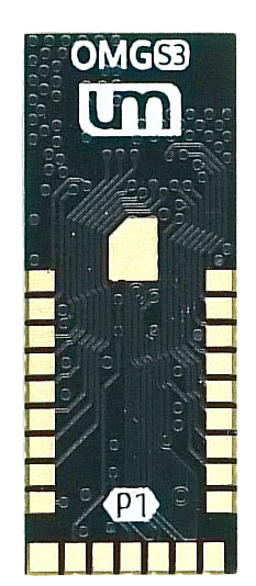
How to Use OMGS3: Examples, Pinouts, and Specs
Introduction
The OMGS3 is a versatile microcontroller designed for a wide range of applications, particularly in the Internet of Things (IoT) and smart device domains. It features integrated Wi-Fi and Bluetooth capabilities, enabling seamless wireless communication. With its powerful processing capabilities and low power consumption, the OMGS3 is ideal for projects such as home automation, wearable devices, industrial monitoring, and more.
Explore Projects Built with OMGS3

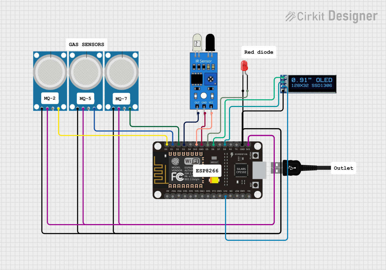


Explore Projects Built with OMGS3
Technical Specifications
The OMGS3 microcontroller offers robust performance and connectivity features. Below are its key technical details:
General Specifications
- Processor: Dual-core 32-bit processor
- Clock Speed: Up to 240 MHz
- Flash Memory: 4 MB
- RAM: 512 KB
- Connectivity: Wi-Fi (802.11 b/g/n), Bluetooth 4.2 (BLE)
- Operating Voltage: 3.3V
- I/O Pins: 34 GPIO pins
- ADC Channels: 12-bit, 18 channels
- PWM Outputs: 16 channels
- Operating Temperature: -40°C to 85°C
Pin Configuration and Descriptions
The OMGS3 has a total of 38 pins, including power, communication, and GPIO pins. Below is the pin configuration:
| Pin Name | Type | Description |
|---|---|---|
| VIN | Power Input | Input voltage (5V) for powering the microcontroller. |
| 3V3 | Power Output | Regulated 3.3V output for external components. |
| GND | Ground | Ground connection. |
| GPIO0-GPIO34 | GPIO | General-purpose input/output pins. |
| ADC0-ADC17 | Analog Input | 12-bit ADC channels for analog signal input. |
| TXD0, RXD0 | UART | UART communication pins (TX and RX). |
| SCL, SDA | I2C | I2C communication pins (clock and data). |
| MOSI, MISO, SCK, CS | SPI | SPI communication pins. |
| EN | Enable | Enable pin to activate the microcontroller. |
| RST | Reset | Reset pin to restart the microcontroller. |
Usage Instructions
The OMGS3 microcontroller is easy to integrate into various projects. Below are the steps and best practices for using it effectively:
Basic Setup
Powering the OMGS3:
- Connect the VIN pin to a 5V power source or use the USB interface for power.
- Ensure the GND pin is connected to the ground of your circuit.
Programming the OMGS3:
- Use a USB-to-serial adapter or a compatible development board to upload code.
- The OMGS3 is compatible with the Arduino IDE, PlatformIO, and other development environments.
Connecting Peripherals:
- Use GPIO pins for digital input/output.
- Connect sensors or analog devices to ADC pins.
- For communication, use UART, I2C, or SPI interfaces as required.
Example: Connecting to Wi-Fi with Arduino IDE
Below is an example code snippet to connect the OMGS3 to a Wi-Fi network:
#include <WiFi.h> // Include the Wi-Fi library for OMGS3

const char* ssid = "Your_SSID";       // Replace with your Wi-Fi network name
const char* password = "Your_Password"; // Replace with your Wi-Fi password

void setup() {
  Serial.begin(115200); // Initialize serial communication
  WiFi.begin(ssid, password); // Start Wi-Fi connection

  Serial.print("Connecting to Wi-Fi");
  while (WiFi.status() != WL_CONNECTED) {
    delay(500);
    Serial.print("."); // Print dots while connecting
  }

  Serial.println("\nConnected to Wi-Fi!");
  Serial.print("IP Address: ");
  Serial.println(WiFi.localIP()); // Print the assigned IP address
}

void loop() {
  // Add your main code here
}
Best Practices
- Always use a stable 3.3V power supply to avoid damaging the microcontroller.
- Use pull-up or pull-down resistors for GPIO pins when necessary.
- Avoid exceeding the maximum current rating of the pins (12mA per pin).
- Use level shifters if interfacing with 5V logic devices.
Troubleshooting and FAQs
Common Issues and Solutions
The OMGS3 is not powering on:
- Ensure the VIN pin is receiving 5V or the USB connection is secure.
- Check for loose connections or damaged cables.
Wi-Fi connection fails:
- Verify the SSID and password in your code.
- Ensure the Wi-Fi network is within range and operational.
- Restart the microcontroller and router if necessary.
Code upload fails:
- Check the USB connection and ensure the correct COM port is selected.
- Press and hold the EN (Enable) button while uploading the code.
GPIO pins not responding:
- Verify the pin mode is correctly set in your code (e.g.,
pinMode(pin, OUTPUT)). - Check for short circuits or incorrect wiring.
- Verify the pin mode is correctly set in your code (e.g.,
FAQs
Can the OMGS3 operate on battery power? Yes, the OMGS3 can be powered using a 3.7V LiPo battery with a suitable voltage regulator.
What is the maximum Wi-Fi range? The Wi-Fi range depends on environmental factors but typically extends up to 50 meters indoors and 100 meters outdoors.
Is the OMGS3 compatible with Arduino libraries? Yes, the OMGS3 supports most Arduino libraries, especially those for Wi-Fi and Bluetooth.
How do I reset the OMGS3? Use the RST pin or press the reset button on the development board.
By following this documentation, you can effectively utilize the OMGS3 microcontroller in your projects.