
How to Use Massive Esp32 RC: Examples, Pinouts, and Specs
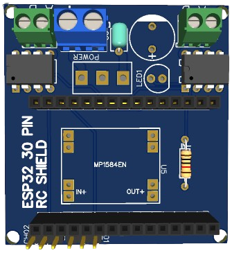
 Design with Massive Esp32 RC in Cirkit Designer
Massive Esp32 RC Documentation
1. Introduction
The Massive Esp32 RC is a versatile development board based on the ESP32 microcontroller. It features built-in Wi-Fi and Bluetooth capabilities, making it an ideal choice for Internet of Things (IoT) projects and remote control applications. This board is designed to provide a robust platform for developing a wide range of applications, from simple sensor networks to complex automation systems.
Common Applications and Use Cases
- Home Automation: Control lights, appliances, and other devices remotely.
- IoT Projects: Connect sensors and actuators to the internet for data collection and control.
- Remote Control: Develop remote control systems for drones, robots, and other devices.
- Wireless Communication: Implement Wi-Fi and Bluetooth communication in various projects.
- Prototyping: Rapidly prototype and test new ideas and concepts.
2. Technical Specifications
Key Technical Details
| Parameter | Value |
|---|---|
| Microcontroller | ESP32 |
| Operating Voltage | 3.3V |
| Input Voltage | 5V (via USB) |
| Digital I/O Pins | 34 |
| Analog Input Pins | 16 (12-bit ADC) |
| Analog Output Pins | 2 (8-bit DAC) |
| Flash Memory | 4MB |
| SRAM | 520KB |
| Wi-Fi | 802.11 b/g/n |
| Bluetooth | v4.2 BR/EDR and BLE |
| Dimensions | 51mm x 25.4mm |
Pin Configuration and Descriptions
| Pin Number | Pin Name | Description |
|---|---|---|
| 1 | EN | Enable pin (active high) |
| 2 | IO0 | GPIO0, used for boot mode selection |
| 3 | IO1 | GPIO1, UART0 TX |
| 4 | IO2 | GPIO2, ADC2_CH2 |
| 5 | IO3 | GPIO3, UART0 RX |
| 6 | IO4 | GPIO4, ADC2_CH0 |
| 7 | IO5 | GPIO5, ADC2_CH1 |
| 8 | IO12 | GPIO12, ADC2_CH5, HSPI MISO |
| 9 | IO13 | GPIO13, ADC2_CH4, HSPI MOSI |
| 10 | IO14 | GPIO14, ADC2_CH6, HSPI CLK |
| 11 | IO15 | GPIO15, ADC2_CH3, HSPI CS0 |
| 12 | IO16 | GPIO16, UART2 RX |
| 13 | IO17 | GPIO17, UART2 TX |
| 14 | IO18 | GPIO18, VSPI CLK |
| 15 | IO19 | GPIO19, VSPI MISO |
| 16 | IO21 | GPIO21, I2C SDA |
| 17 | IO22 | GPIO22, I2C SCL |
| 18 | IO23 | GPIO23, VSPI MOSI |
| 19 | IO25 | GPIO25, DAC1, ADC2_CH8 |
| 20 | IO26 | GPIO26, DAC2, ADC2_CH9 |
| 21 | IO27 | GPIO27, ADC2_CH7 |
| 22 | IO32 | GPIO32, ADC1_CH4 |
| 23 | IO33 | GPIO33, ADC1_CH5 |
| 24 | IO34 | GPIO34, ADC1_CH6 |
| 25 | IO35 | GPIO35, ADC1_CH7 |
| 26 | GND | Ground |
| 27 | 3V3 | 3.3V power supply |
| 28 | VIN | Input voltage (5V via USB) |
3. Usage Instructions
How to Use the Component in a Circuit
Powering the Board:
- Connect the board to a computer or a USB power adapter using a micro-USB cable.
- Ensure the input voltage is 5V via the USB connection.
Connecting to Wi-Fi:
- Use the built-in Wi-Fi module to connect to a wireless network.
- Configure the Wi-Fi settings in your code to connect to the desired network.
Using GPIO Pins:
- Connect sensors, actuators, and other peripherals to the GPIO pins.
- Configure the pins as input or output in your code.
Programming the Board:
- Use the Arduino IDE or other compatible development environments.
- Select "ESP32 Dev Module" as the board type in the Arduino IDE.
Important Considerations and Best Practices
- Voltage Levels: Ensure all connected peripherals operate at 3.3V logic levels to avoid damaging the board.
- Pin Usage: Avoid using GPIO pins that are shared with other functions (e.g., boot mode selection) unless necessary.
- Heat Management: The ESP32 can generate heat during operation. Ensure proper ventilation or heat dissipation if used in enclosed spaces.
- Firmware Updates: Regularly update the firmware to benefit from the latest features and security patches.
4. Example Code
Here is an example code to connect the Massive Esp32 RC to a Wi-Fi network and control an LED connected to GPIO2:
#include <WiFi.h>

// Replace with your network credentials
const char* ssid = "your_SSID";
const char* password = "your_PASSWORD";

void setup() {
  // Initialize serial communication
  Serial.begin(115200);

  // Initialize GPIO2 as an output pin
  pinMode(2, OUTPUT);

  // Connect to Wi-Fi
  Serial.print("Connecting to ");
  Serial.println(ssid);
  WiFi.begin(ssid, password);

  while (WiFi.status() != WL_CONNECTED) {
    delay(1000);
    Serial.print(".");
  }

  Serial.println("");
  Serial.println("WiFi connected.");
  Serial.println("IP address: ");
  Serial.println(WiFi.localIP());
}

void loop() {
  // Turn the LED on
  digitalWrite(2, HIGH);
  delay(1000); // Wait for a second

  // Turn the LED off
  digitalWrite(2, LOW);
  delay(1000); // Wait for a second
}
5. Troubleshooting and FAQs
Common Issues Users Might Face
Wi-Fi Connection Issues:
- Ensure the SSID and password are correct.
- Check if the Wi-Fi network is within range.
- Restart the router and the ESP32 board.
Board Not Recognized by Computer:
- Ensure the USB cable is properly connected.
- Try a different USB cable or port.
- Install the necessary drivers for the ESP32.
GPIO Pin Not Working:
- Check the pin configuration in the code.
- Ensure the connected peripheral is functioning correctly.
- Verify the voltage levels are appropriate.
Solutions and Tips for Troubleshooting
- Serial Monitor: Use the Serial Monitor in the Arduino IDE to debug and print messages.
- Firmware Updates: Ensure the board's firmware is up to date.
- Community Support: Utilize online forums and communities for additional support and troubleshooting tips.
By following this documentation, users can effectively utilize the Massive Esp32 RC for their projects, ensuring a smooth and efficient development process.
Explore Projects Built with Massive Esp32 RC
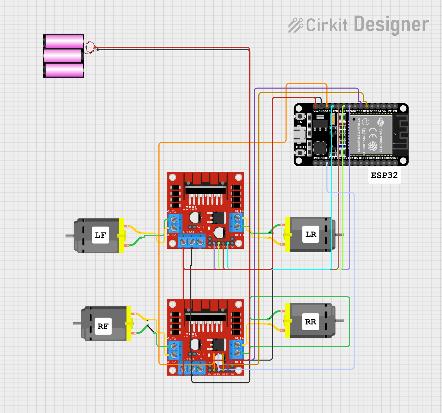
 Open Project in Cirkit Designer
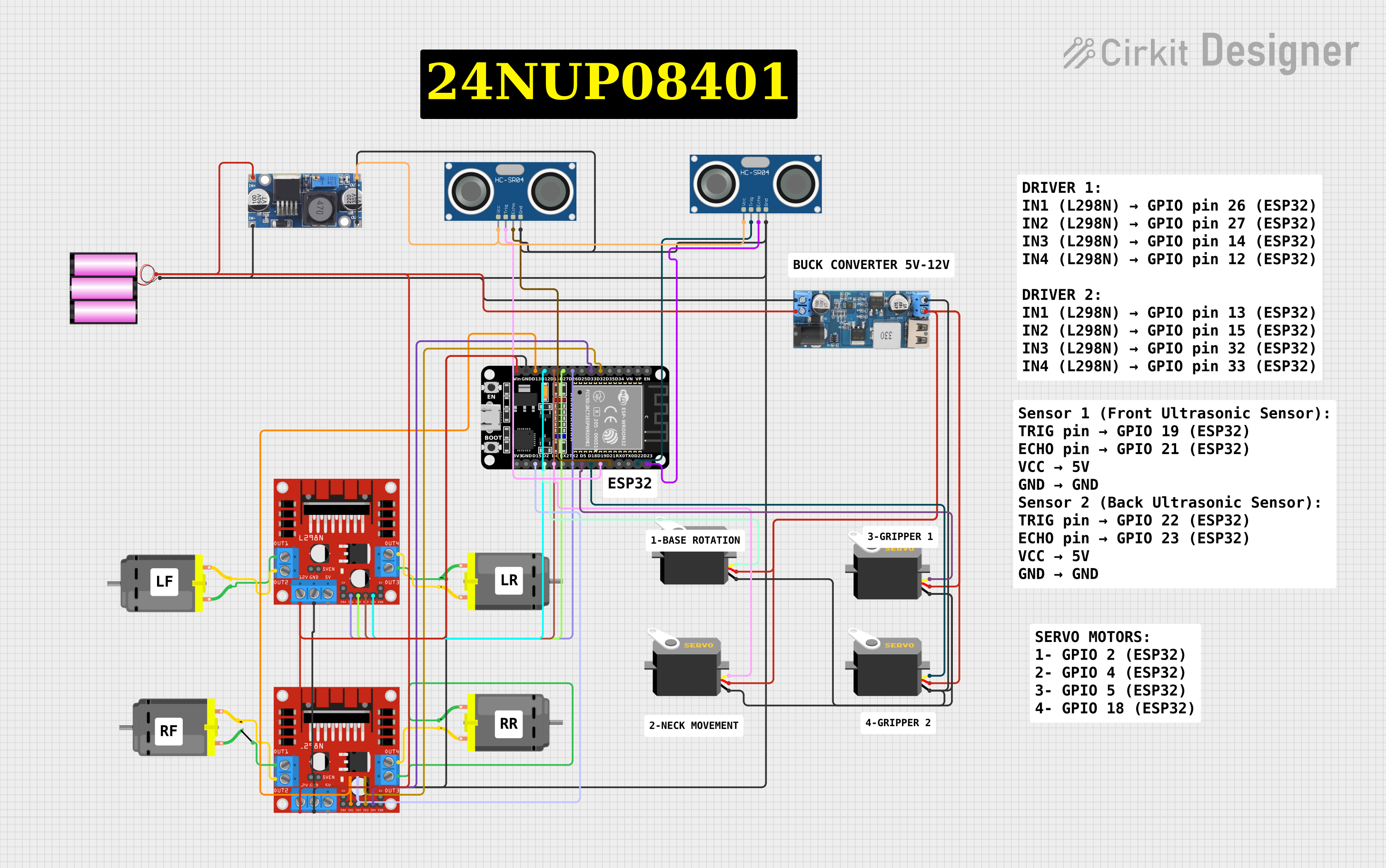
 Open Project in Cirkit Designer
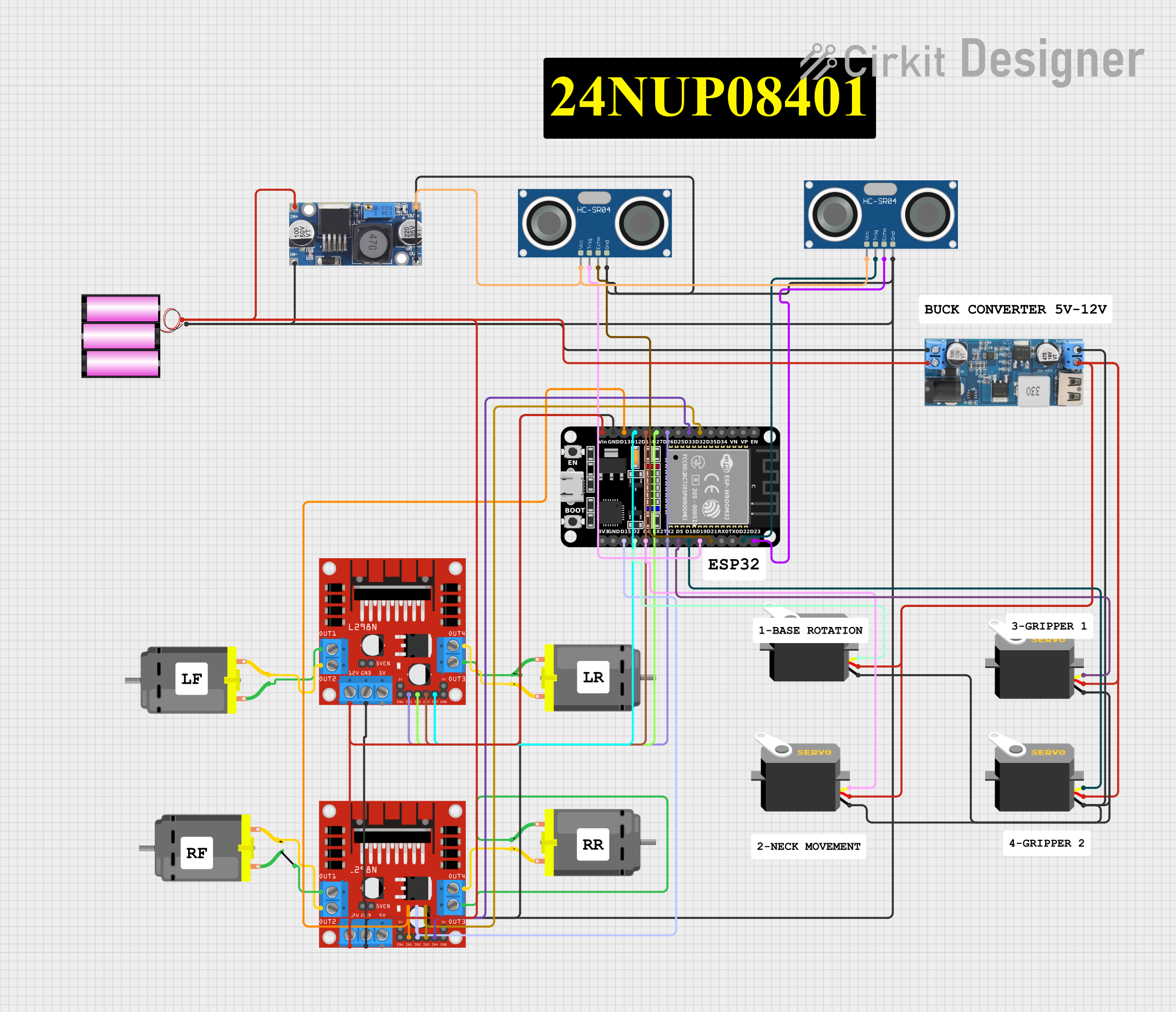
 Open Project in Cirkit Designer
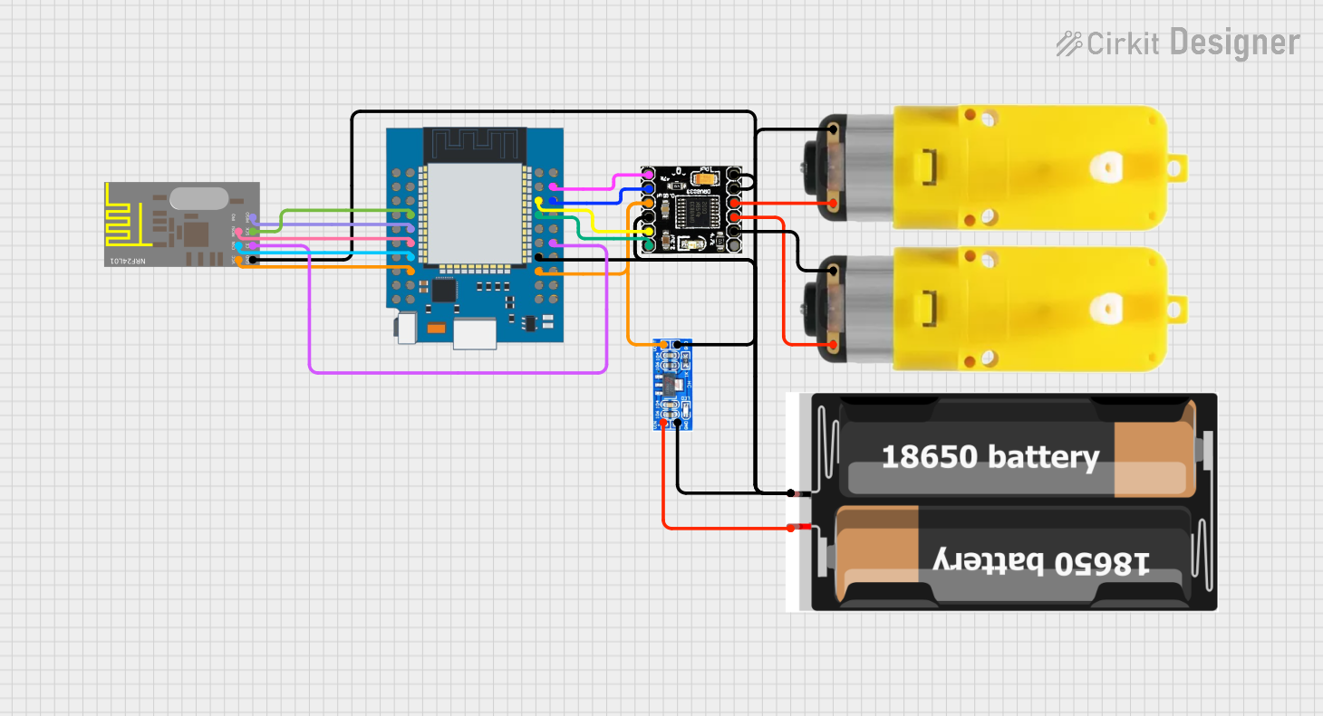
 Open Project in Cirkit Designer
Explore Projects Built with Massive Esp32 RC

 Open Project in Cirkit Designer
 Open Project in Cirkit Designer
 Open Project in Cirkit Designer
 Open Project in Cirkit Designer