How to Use LED: Two Pin (red) - Long Pins: Examples, Pinouts, and Specs
Introduction
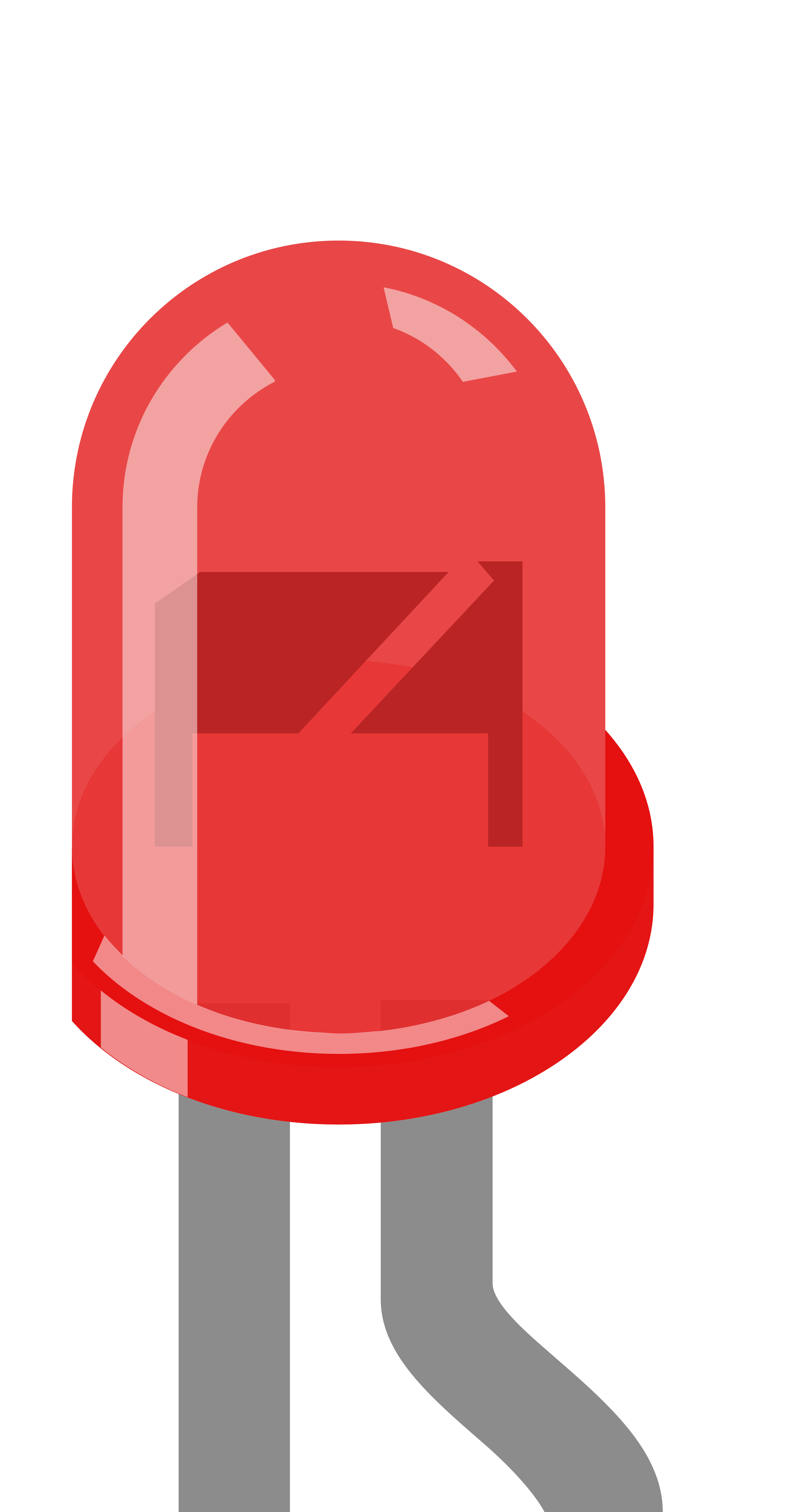
The Two Pin Red LED is a light-emitting diode that emits bright red light when powered. It features two pins: a longer pin (anode) and a shorter pin (cathode), making it easy to identify polarity. The long pins are particularly useful for breadboard prototyping and soldering in electronic circuits. This LED is widely used in indicator lights, status displays, and decorative lighting applications due to its simplicity, low power consumption, and reliability.
Explore Projects Built with LED: Two Pin (red) - Long Pins

Explore Projects Built with LED: Two Pin (red) - Long Pins
Common Applications:
- Power and status indicators in electronic devices
- DIY electronics and prototyping
- Signal and warning lights
- Decorative and ambient lighting
- Educational projects for learning basic electronics
Technical Specifications
Below are the key technical details for the Two Pin Red LED:
| Parameter | Value |
|---|---|
| Forward Voltage (Vf) | 1.8V to 2.2V |
| Forward Current (If) | 20mA (typical) |
| Maximum Current (Imax) | 30mA |
| Wavelength | 620nm to 630nm (red light) |
| Viewing Angle | 20° to 30° |
| Operating Temperature | -40°C to +85°C |
| Pin Length | Anode: ~25mm, Cathode: ~20mm |
Pin Configuration:
| Pin | Name | Description |
|---|---|---|
| Long Pin | Anode | Positive terminal; connect to the positive voltage. |
| Short Pin | Cathode | Negative terminal; connect to ground (GND). |
Usage Instructions
How to Use the LED in a Circuit
Identify the Pins: The longer pin is the anode (positive), and the shorter pin is the cathode (negative).
Connect to Power:
- Connect the anode to the positive voltage source through a current-limiting resistor.
- Connect the cathode to the ground (GND).
Choose a Resistor: To prevent damage, calculate the resistor value using Ohm's Law: [ R = \frac{V_{supply} - V_f}{I_f} ]
- (V_{supply}): Supply voltage (e.g., 5V for Arduino).
- (V_f): Forward voltage of the LED (1.8V to 2.2V).
- (I_f): Desired forward current (e.g., 20mA or 0.02A).
Example: For a 5V supply and 20mA current: [ R = \frac{5V - 2V}{0.02A} = 150\Omega ] Use a 150Ω resistor.
Insert into Circuit: Place the LED and resistor in series. Ensure correct polarity.
Example: Connecting to an Arduino UNO
Below is an example of how to connect the LED to an Arduino UNO and blink it:
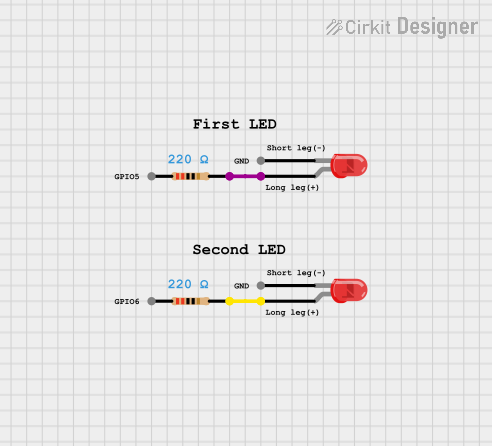
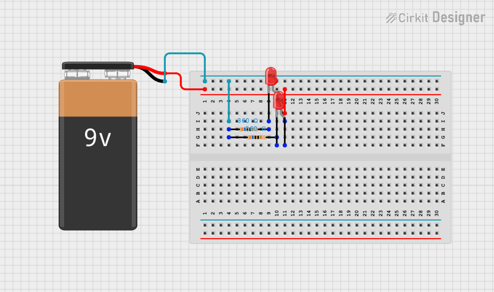
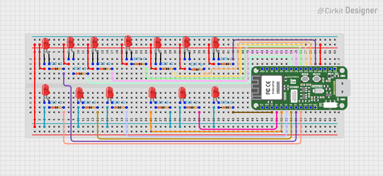
Circuit Setup:
- Connect the anode (long pin) of the LED to a 220Ω resistor.
- Connect the other end of the resistor to Arduino pin 13.
- Connect the cathode (short pin) of the LED to the Arduino GND pin.
Arduino Code:
// LED Blink Example for Two Pin Red LED
// Connect the LED anode to pin 13 through a 220Ω resistor
// Connect the LED cathode to GND

void setup() {
  pinMode(13, OUTPUT); // Set pin 13 as an output
}

void loop() {
  digitalWrite(13, HIGH); // Turn the LED on
  delay(1000);            // Wait for 1 second
  digitalWrite(13, LOW);  // Turn the LED off
  delay(1000);            // Wait for 1 second
}
Important Considerations:
- Polarity: LEDs are polarized components. Reversing the polarity may damage the LED.
- Current Limiting: Always use a resistor to limit current and prevent overheating.
- Brightness Control: Use Pulse Width Modulation (PWM) on Arduino PWM pins to adjust brightness.
Troubleshooting and FAQs
Common Issues:
LED Does Not Light Up:
Cause: Incorrect polarity.
Solution: Ensure the anode is connected to the positive voltage and the cathode to GND.
Cause: No current-limiting resistor or incorrect resistor value.
Solution: Use a resistor with the correct value (e.g., 150Ω for 5V supply).
LED is Dim:
- Cause: Resistor value too high.
- Solution: Recalculate the resistor value for the desired brightness.
LED Burns Out:
- Cause: Excessive current due to missing or low-value resistor.
- Solution: Always use a resistor to limit current.
Flickering LED:
- Cause: Unstable power supply or loose connections.
- Solution: Check power supply and ensure all connections are secure.
FAQs:
Q: Can I connect the LED directly to a 3.3V or 5V supply?
A: No, always use a current-limiting resistor to prevent damage.Q: How do I make the LED brighter?
A: Reduce the resistor value slightly, but ensure the current does not exceed 20mA.Q: Can I use this LED with a 12V power supply?
A: Yes, but you must calculate and use an appropriate resistor to limit the current.Q: Can I use this LED for PWM dimming?
A: Yes, connect it to a PWM-capable pin on a microcontroller like Arduino.
By following these guidelines, you can effectively use the Two Pin Red LED in your projects!