How to Use LILYGO AMOLED 1.64 ESP32 S3: Examples, Pinouts, and Specs
Introduction
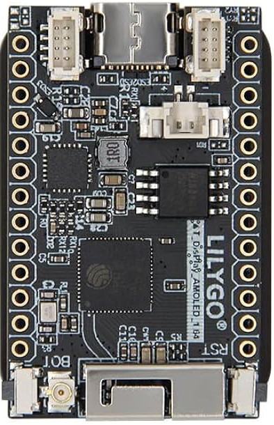
The LILYGO AMOLED 1.64 ESP32 S3 is a compact development board that integrates a 1.64-inch AMOLED display with the powerful ESP32-S3 microcontroller. This versatile board is designed for IoT projects, wearable devices, and other applications requiring a high-resolution display and wireless connectivity. With built-in Wi-Fi and Bluetooth capabilities, it is an excellent choice for developers looking to create innovative and connected solutions.
Explore Projects Built with LILYGO AMOLED 1.64 ESP32 S3

Explore Projects Built with LILYGO AMOLED 1.64 ESP32 S3
Common Applications and Use Cases
- Wearable devices (e.g., smartwatches, fitness trackers)
- IoT dashboards and control panels
- Portable data visualization tools
- Wireless communication projects
- Educational and prototyping purposes
Technical Specifications
Key Technical Details
| Feature | Specification |
|---|---|
| Microcontroller | ESP32-S3 dual-core Xtensa LX7 |
| Display | 1.64-inch AMOLED, 280x456 resolution |
| Wireless Connectivity | Wi-Fi 802.11 b/g/n, Bluetooth 5.0 LE |
| Flash Memory | 16 MB |
| PSRAM | 8 MB |
| Operating Voltage | 3.3V |
| Power Supply | USB-C (5V input) |
| GPIO Pins | 14 (configurable for various peripherals) |
| Communication Interfaces | I2C, SPI, UART |
| Dimensions | 44mm x 30mm |
Pin Configuration and Descriptions
| Pin | Name | Description |
|---|---|---|
| 1 | GND | Ground |
| 2 | 3V3 | 3.3V power output |
| 3 | GPIO0 | General-purpose I/O, can be used for boot mode |
| 4 | GPIO1 | General-purpose I/O |
| 5 | GPIO2 | General-purpose I/O |
| 6 | GPIO3 | General-purpose I/O |
| 7 | SDA | I2C data line |
| 8 | SCL | I2C clock line |
| 9 | MOSI | SPI data out |
| 10 | MISO | SPI data in |
| 11 | SCK | SPI clock |
| 12 | RX | UART receive |
| 13 | TX | UART transmit |
| 14 | RST | Reset pin |
Usage Instructions
How to Use the Component in a Circuit
- Powering the Board: Connect the board to a USB-C power source (5V input). The onboard voltage regulator will provide the required 3.3V for the ESP32-S3 and other components.
- Connecting Peripherals: Use the GPIO pins to connect sensors, actuators, or other peripherals. Ensure that the voltage levels of connected devices are compatible with the 3.3V logic of the board.
- Programming the Board: The board can be programmed using the Arduino IDE, PlatformIO, or the ESP-IDF framework. Install the necessary drivers and libraries for the ESP32-S3 and the AMOLED display.
Important Considerations and Best Practices
- Power Supply: Ensure a stable 5V power supply to avoid voltage fluctuations that could affect performance.
- Display Handling: Avoid applying excessive pressure to the AMOLED display to prevent damage.
- GPIO Usage: Check the ESP32-S3 datasheet for pin-specific limitations and avoid using reserved pins.
- Heat Management: The ESP32-S3 may generate heat during operation. Ensure proper ventilation if used in enclosed spaces.
Example Code for Arduino UNO
Below is an example of how to initialize the AMOLED display and print text using the Arduino IDE:
#include <Wire.h>
#include <Adafruit_GFX.h>
#include <Adafruit_SSD1351.h>

// Define display pins
#define OLED_CS    5   // Chip select pin
#define OLED_DC    16  // Data/command pin
#define OLED_RST   17  // Reset pin

// Initialize the display (280x456 resolution)
Adafruit_SSD1351 display = Adafruit_SSD1351(280, 456, &SPI, OLED_CS, OLED_DC, OLED_RST);

void setup() {
  // Initialize serial communication for debugging
  Serial.begin(115200);
  Serial.println("Initializing display...");

  // Initialize the display
  if (!display.begin()) {
    Serial.println("Failed to initialize display!");
    while (1); // Halt execution if initialization fails
  }

  // Clear the display and set text color
  display.fillScreen(SSD1351_BLACK);
  display.setTextColor(SSD1351_WHITE);

  // Display a message
  display.setCursor(10, 10);
  display.setTextSize(2);
  display.println("Hello, LILYGO!");
  display.display();
}

void loop() {
  // Add your main code here
}
Notes:
- Install the Adafruit GFX and Adafruit SSD1351 libraries in the Arduino IDE before running the code.
- Modify the pin definitions (
OLED_CS,OLED_DC,OLED_RST) if your setup uses different pins.
Troubleshooting and FAQs
Common Issues and Solutions
Display Not Turning On:
- Ensure the board is receiving power (check the USB-C connection).
- Verify that the display pins are correctly connected and match the pin definitions in your code.
Program Upload Fails:
- Check that the correct COM port and board type are selected in the Arduino IDE.
- Hold the BOOT button on the board while uploading the code to enter bootloader mode.
Wi-Fi or Bluetooth Not Working:
- Ensure that the ESP32-S3 firmware is up to date.
- Verify that the Wi-Fi credentials or Bluetooth pairing process is correctly implemented in your code.
Overheating:
- Avoid running the board at maximum performance for extended periods without proper ventilation.
- Use a heat sink if necessary for high-performance applications.
FAQs
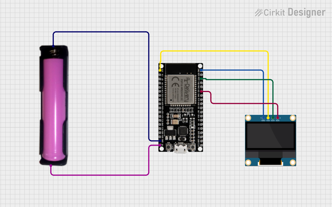
Can I power the board with a battery? Yes, the board supports battery operation. Use a compatible LiPo battery and connect it to the designated JST connector.
What is the maximum current draw of the board? The maximum current draw depends on the peripherals and Wi-Fi/Bluetooth usage but typically ranges between 200-500mA.
Is the display touch-enabled? No, the 1.64-inch AMOLED display does not have touch functionality.
Can I use this board with MicroPython? Yes, the ESP32-S3 is compatible with MicroPython. Flash the MicroPython firmware and use the appropriate libraries for the display.
This concludes the documentation for the LILYGO AMOLED 1.64 ESP32 S3.