How to Use Bipolar Stepper Motor (NEMA 17): Examples, Pinouts, and Specs
Introduction
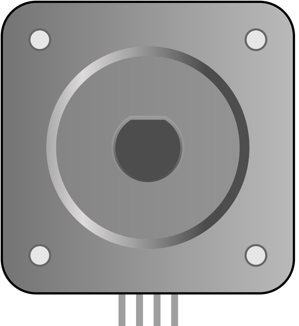
The Bipolar Stepper Motor (NEMA 17) is a type of stepper motor characterized by its two coils and four wires. It is widely used in applications requiring precise control of movement, such as 3D printers, CNC machines, and robotics. The NEMA 17 designation refers to the motor's frame size, which is 1.7 inches (43.2 mm) square. This motor is known for its reliability, accuracy, and ease of use in various motion control applications.
Explore Projects Built with Bipolar Stepper Motor (NEMA 17)
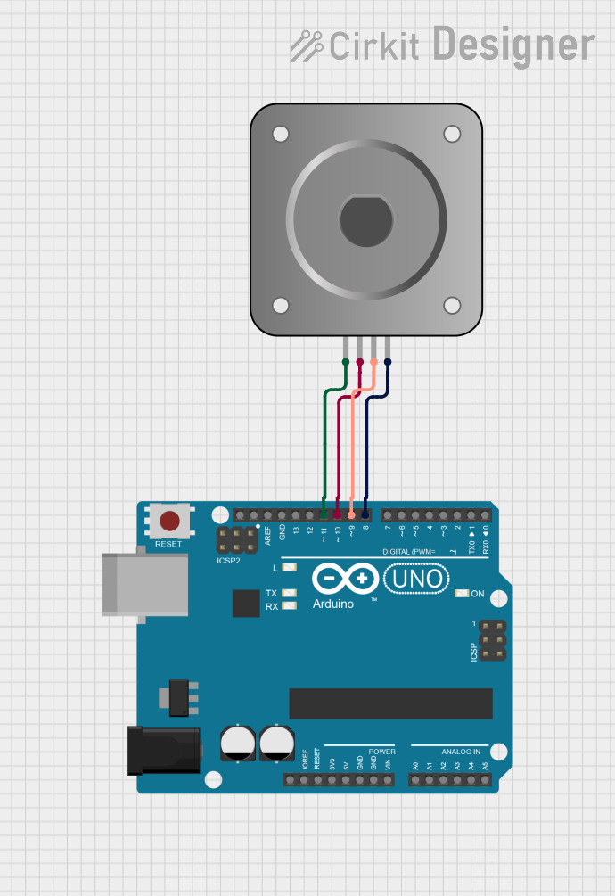
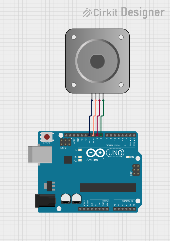
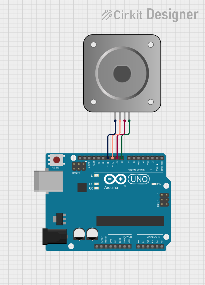
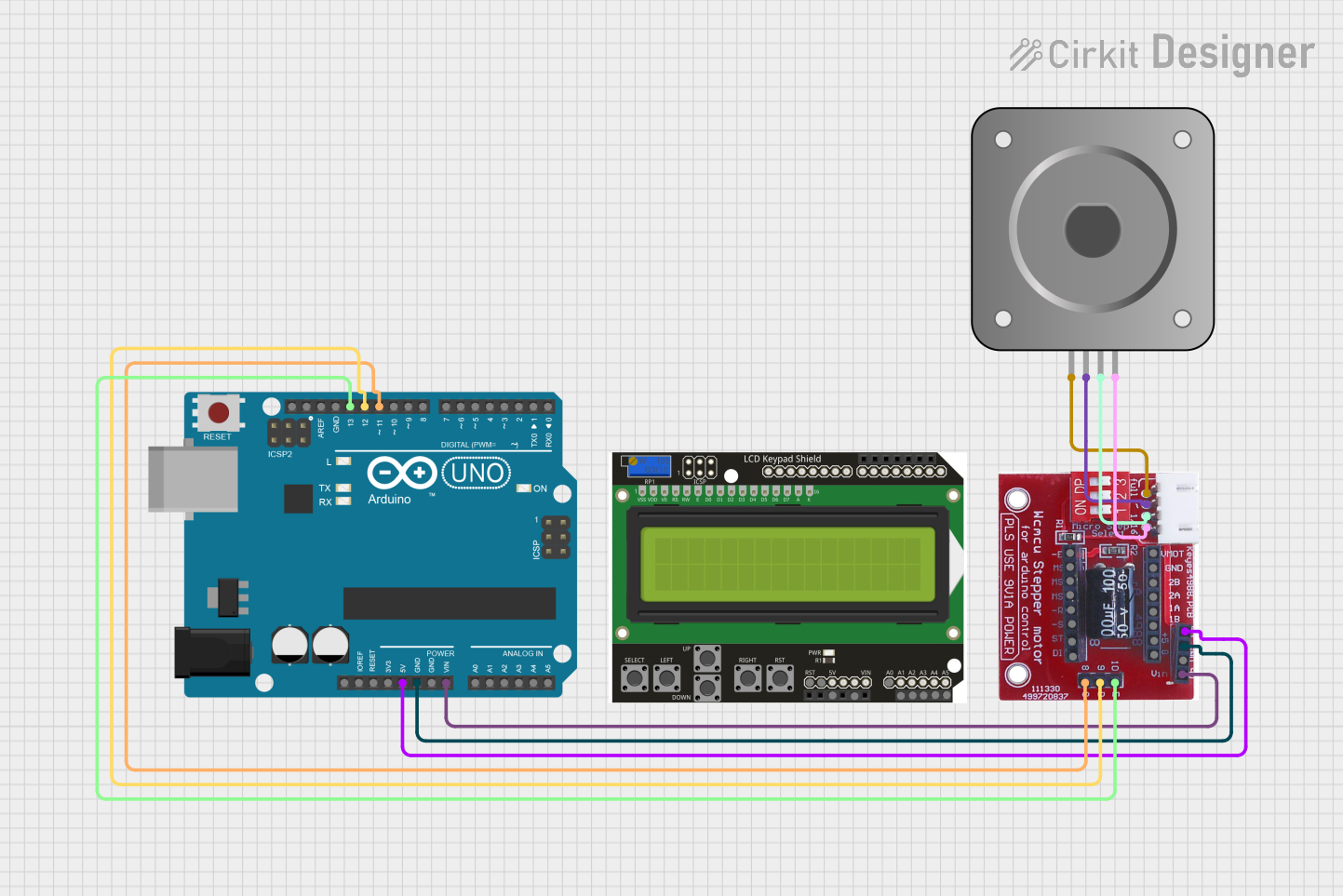
Explore Projects Built with Bipolar Stepper Motor (NEMA 17)
Technical Specifications
Key Technical Details
| Parameter | Value |
|---|---|
| Frame Size | 1.7 inches (43.2 mm) |
| Step Angle | 1.8 degrees |
| Holding Torque | 45 Ncm (64 oz.in) |
| Rated Current | 1.5 A per phase |
| Voltage | 12V |
| Resistance | 2.8 ohms per phase |
| Inductance | 3.2 mH per phase |
| Number of Leads | 4 |
| Shaft Diameter | 5 mm |
| Shaft Length | 24 mm |
| Weight | 280 g |
Pin Configuration and Descriptions
| Pin Number | Wire Color | Description |
|---|---|---|
| 1 | Red | Coil A |
| 2 | Blue | Coil A |
| 3 | Green | Coil B |
| 4 | Black | Coil B |
Usage Instructions
How to Use the Component in a Circuit
To use the Bipolar Stepper Motor (NEMA 17) in a circuit, you will need a stepper motor driver, such as the A4988 or DRV8825, and a microcontroller, such as the Arduino UNO. The driver will control the current to the motor coils, allowing for precise movement.
Connect the Motor to the Driver:
- Connect the Red and Blue wires to the A+ and A- terminals of the driver.
- Connect the Green and Black wires to the B+ and B- terminals of the driver.
Connect the Driver to the Arduino:
- Connect the STEP pin of the driver to a digital pin on the Arduino (e.g., pin 2).
- Connect the DIR pin of the driver to another digital pin on the Arduino (e.g., pin 3).
- Connect the EN (Enable) pin to a digital pin on the Arduino (optional, for enabling/disabling the motor).
Power the Driver:
- Connect the VCC and GND pins of the driver to the 5V and GND pins of the Arduino.
- Connect the motor power supply (e.g., 12V) to the VMOT and GND pins of the driver.
Important Considerations and Best Practices
- Current Limiting: Adjust the current limit on the driver to match the rated current of the motor (1.5 A per phase) to prevent overheating and damage.
- Cooling: Ensure adequate cooling for the driver and motor, especially in high-current applications.
- Microstepping: Use microstepping settings on the driver to achieve smoother and more precise movement.
Sample Arduino Code
// Define stepper motor connections and steps per revolution
#define dirPin 3
#define stepPin 2
#define stepsPerRevolution 200

void setup() {
  // Set the direction and step pins as outputs
  pinMode(stepPin, OUTPUT);
  pinMode(dirPin, OUTPUT);
}

void loop() {
  // Set the direction clockwise
  digitalWrite(dirPin, HIGH);

  // Step the motor one revolution
  for (int i = 0; i < stepsPerRevolution; i++) {
    digitalWrite(stepPin, HIGH);
    delayMicroseconds(1000); // Adjust delay for speed control
    digitalWrite(stepPin, LOW);
    delayMicroseconds(1000);
  }

  delay(1000); // Wait for a second

  // Set the direction counterclockwise
  digitalWrite(dirPin, LOW);

  // Step the motor one revolution
  for (int i = 0; i < stepsPerRevolution; i++) {
    digitalWrite(stepPin, HIGH);
    delayMicroseconds(1000);
    digitalWrite(stepPin, LOW);
    delayMicroseconds(1000);
  }

  delay(1000); // Wait for a second
}
Troubleshooting and FAQs
Common Issues Users Might Face
Motor Not Moving:
- Solution: Check all connections between the motor, driver, and Arduino. Ensure the power supply is connected and providing the correct voltage.
Motor Vibrates but Doesn't Rotate:
- Solution: Verify the wiring of the motor coils. Ensure that the coils are connected to the correct terminals on the driver.
Overheating:
- Solution: Adjust the current limit on the driver to match the motor's rated current. Ensure proper cooling and ventilation.
Inconsistent Movement:
- Solution: Check for loose connections and ensure the power supply is stable. Use microstepping to achieve smoother movement.
Solutions and Tips for Troubleshooting
- Double-Check Wiring: Ensure that all connections are secure and correctly matched to the driver and motor specifications.
- Use a Multimeter: Measure the voltage and current at various points in the circuit to diagnose issues.
- Consult Datasheets: Refer to the datasheets of the motor and driver for detailed specifications and troubleshooting tips.
- Test with Simple Code: Use basic code examples to test the motor and driver functionality before integrating into a larger project.
By following this documentation, users can effectively utilize the Bipolar Stepper Motor (NEMA 17) in their projects, ensuring precise and reliable control of movement.