How to Use LM35DT: Examples, Pinouts, and Specs
Introduction
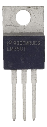
The LM35DT is a precision integrated-circuit temperature sensor with an output voltage linearly proportional to the Celsius temperature. It requires no external calibration or trimming to provide typical accuracies of ±0.25°C at room temperature and ±0.75°C over a full -55°C to +150°C temperature range. This makes it an ideal choice for a wide range of temperature sensing applications.
Explore Projects Built with LM35DT


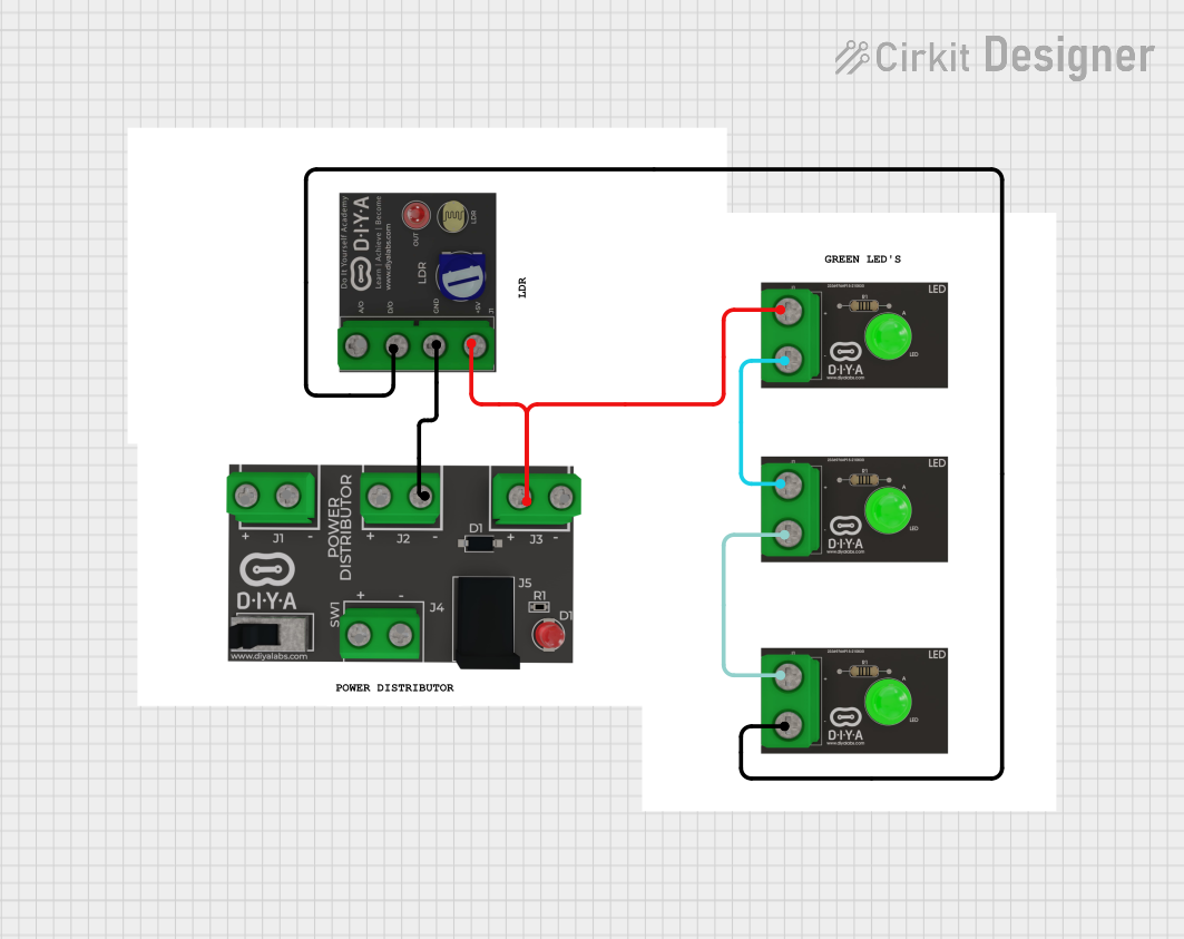
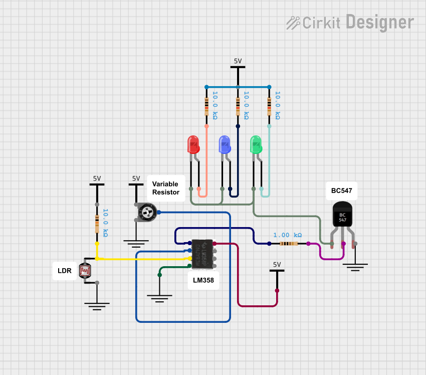
Explore Projects Built with LM35DT
Common Applications and Use Cases
- Environmental Monitoring: Used in weather stations and environmental monitoring systems.
- Industrial Automation: Employed in industrial processes to monitor and control temperature.
- Consumer Electronics: Integrated into devices like thermostats and home automation systems.
- Medical Devices: Utilized in medical equipment for temperature monitoring.
- Automotive: Used in vehicles for engine and cabin temperature monitoring.
Technical Specifications
Key Technical Details
| Parameter | Value |
|---|---|
| Supply Voltage Range | 4V to 30V |
| Supply Current | 60 µA |
| Output Voltage Range | 0V to 5V |
| Temperature Range | -55°C to +150°C |
| Accuracy at 25°C | ±0.25°C |
| Accuracy over full range | ±0.75°C |
| Sensitivity | 10 mV/°C |
| Response Time | 1.5 seconds (typical) |
Pin Configuration and Descriptions
| Pin Number | Pin Name | Description |
|---|---|---|
| 1 | Vout | Output voltage proportional to temperature |
| 2 | GND | Ground |
| 3 | Vs | Supply voltage (4V to 30V) |
Usage Instructions
How to Use the LM35DT in a Circuit
- Power Supply: Connect the Vs pin (Pin 3) to a power supply ranging from 4V to 30V.
- Ground Connection: Connect the GND pin (Pin 2) to the ground of the circuit.
- Output Voltage: The Vout pin (Pin 1) will provide an output voltage that is linearly proportional to the temperature in Celsius. For example, at 25°C, the output voltage will be 250 mV.
Important Considerations and Best Practices
- Decoupling Capacitor: Place a 0.1 µF capacitor between Vs and GND to filter out noise.
- Wiring: Keep the wiring short to minimize noise pickup.
- Calibration: Although the LM35DT does not require external calibration, ensure that the sensor is placed in a stable environment for accurate readings.
- Heat Sources: Avoid placing the sensor near heat sources that could affect its accuracy.
Example Circuit with Arduino UNO
// Example code to read temperature from LM35DT using Arduino UNO

const int sensorPin = A0; // LM35DT output connected to analog pin A0
float temperature;        // Variable to store temperature value

void setup() {
  Serial.begin(9600); // Initialize serial communication at 9600 baud rate
}

void loop() {
  int sensorValue = analogRead(sensorPin); // Read the analog value from the sensor
  temperature = (sensorValue * 5.0 * 100.0) / 1024.0; // Convert the analog value to temperature
  Serial.print("Temperature: ");
  Serial.print(temperature); // Print the temperature value to the serial monitor
  Serial.println(" °C");
  delay(1000); // Wait for 1 second before taking another reading
}
Troubleshooting and FAQs
Common Issues and Solutions
No Output Voltage:
- Solution: Check the power supply connections and ensure that the sensor is receiving the correct voltage.
Inaccurate Readings:
- Solution: Ensure that the sensor is not placed near heat sources or in direct sunlight. Verify that the ground connection is secure.
Fluctuating Readings:
- Solution: Add a decoupling capacitor (0.1 µF) between Vs and GND to filter out noise.
FAQs
Q1: Can the LM35DT be used to measure negative temperatures?
- A1: Yes, the LM35DT can measure temperatures as low as -55°C. The output voltage will be negative for temperatures below 0°C.
Q2: What is the maximum distance between the LM35DT and the microcontroller?
- A2: It is recommended to keep the wiring as short as possible to minimize noise pickup. For longer distances, consider using shielded cables.
Q3: Can the LM35DT be submerged in liquid for temperature measurement?
- A3: No, the LM35DT is not designed to be submerged in liquid. Use a waterproof temperature sensor for such applications.
Q4: How do I calibrate the LM35DT?
- A4: The LM35DT does not require external calibration. However, ensure that the sensor is placed in a stable environment for accurate readings.
By following this documentation, users can effectively integrate the LM35DT temperature sensor into their projects, ensuring accurate and reliable temperature measurements.