How to Use 24V-9V 3A buck converter: Examples, Pinouts, and Specs
Introduction
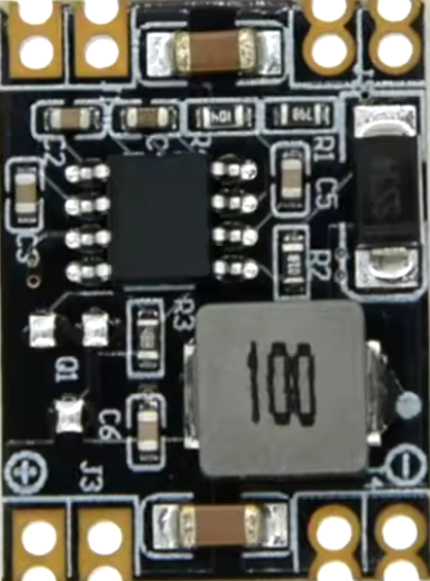
The 24V-9V 3A buck converter is a DC-DC step-down voltage regulator designed to convert a 24V input voltage to a stable 9V output voltage with a maximum output current of 3A. This component is highly efficient, minimizing energy loss during the conversion process, and is widely used in applications requiring a lower voltage supply from a higher voltage source.
Explore Projects Built with 24V-9V 3A buck converter


Explore Projects Built with 24V-9V 3A buck converter
Common Applications and Use Cases
- Powering 9V devices from a 24V power source
- Battery-powered systems requiring efficient voltage regulation
- Industrial automation and control systems
- Robotics and embedded systems
- LED drivers and lighting systems
Technical Specifications
The following table outlines the key technical details of the 24V-9V 3A buck converter:
| Parameter | Value |
|---|---|
| Input Voltage Range | 12V to 24V |
| Output Voltage | 9V |
| Maximum Output Current | 3A |
| Efficiency | Up to 95% |
| Switching Frequency | 150 kHz (typical) |
| Operating Temperature | -40°C to +85°C |
| Dimensions | Varies by model (e.g., 45x25 mm) |
Pin Configuration and Descriptions
The buck converter typically has four pins or terminals. The table below describes each pin:
| Pin Name | Description |
|---|---|
| VIN | Input voltage pin (connect to 24V power source) |
| GND | Ground pin (common ground for input and output) |
| VOUT | Output voltage pin (provides 9V regulated output) |
| EN (optional) | Enable pin (used to turn the converter on/off) |
Usage Instructions
How to Use the Component in a Circuit
Connect the Input Voltage (VIN):
Attach the VIN pin to a 24V DC power source. Ensure the input voltage is within the specified range (12V to 24V) to avoid damaging the converter.Connect the Ground (GND):
Connect the GND pin to the ground of your circuit. This serves as the common reference point for both input and output.Connect the Output Voltage (VOUT):
Attach the VOUT pin to the load or device requiring a 9V power supply. Ensure the load does not exceed the maximum output current of 3A.Optional Enable Pin (EN):
If the converter includes an enable pin, connect it to a logic HIGH signal (e.g., 5V) to activate the converter. Pulling it LOW or leaving it unconnected may disable the output.
Important Considerations and Best Practices
Heat Dissipation:
At high currents, the converter may generate heat. Use a heatsink or ensure proper ventilation to prevent overheating.Input Capacitor:
Place a capacitor (e.g., 100 µF) near the VIN pin to stabilize the input voltage and reduce noise.Output Capacitor:
Add a capacitor (e.g., 47 µF) near the VOUT pin to smooth the output voltage and improve transient response.Load Requirements:
Ensure the connected load does not exceed the maximum output current of 3A to avoid overloading the converter.
Example: Using the Buck Converter with an Arduino UNO
The 24V-9V buck converter can be used to power an Arduino UNO from a 24V power source. Connect the VOUT pin of the converter to the Arduino's VIN pin, which accepts 7-12V.
// Example code to blink an LED using Arduino UNO powered by the buck converter

// Define the LED pin
const int ledPin = 13;

void setup() {
  pinMode(ledPin, OUTPUT); // Set the LED pin as an output
}

void loop() {
  digitalWrite(ledPin, HIGH); // Turn the LED on
  delay(1000);                // Wait for 1 second
  digitalWrite(ledPin, LOW);  // Turn the LED off
  delay(1000);                // Wait for 1 second
}
Troubleshooting and FAQs
Common Issues and Solutions
No Output Voltage:
- Cause: The input voltage is below the minimum required (12V).
Solution: Verify the input voltage and ensure it is within the 12V-24V range. - Cause: The enable pin (EN) is not connected or is pulled LOW.
Solution: Connect the EN pin to a logic HIGH signal (e.g., 5V) or check the datasheet for default behavior.
- Cause: The input voltage is below the minimum required (12V).
Overheating:
- Cause: The load exceeds the maximum output current of 3A.
Solution: Reduce the load or use a higher-rated buck converter. - Cause: Inadequate heat dissipation.
Solution: Add a heatsink or improve airflow around the converter.
- Cause: The load exceeds the maximum output current of 3A.
Output Voltage Fluctuations:
- Cause: Insufficient input or output capacitors.
Solution: Add capacitors as recommended in the usage instructions. - Cause: Noise or interference in the input power supply.
Solution: Use a filtered power source or add an input filter.
- Cause: Insufficient input or output capacitors.
FAQs
Q: Can I use this buck converter to power a 5V device?
A: No, this converter is designed to output 9V. To power a 5V device, use a 24V-5V buck converter or add a 5V linear regulator to the 9V output.
Q: What happens if I connect a load that requires more than 3A?
A: The converter may overheat, shut down, or fail. Always ensure the load current is within the specified limit.
Q: Can I use this converter with an AC power source?
A: No, the buck converter requires a DC input. Use an AC-DC adapter to convert AC to DC before connecting to the converter.