How to Use Quad 2-Input NAND: Examples, Pinouts, and Specs

Introduction
The Quad 2-Input NAND Gate (7400), manufactured by Texas Instruments, is a digital logic gate that outputs a low signal (false) only when both of its two inputs are high (true). It consists of four independent 2-input NAND gates integrated into a single package. This component is widely used in digital circuits for implementing logic functions, such as combinational and sequential logic designs.
Explore Projects Built with Quad 2-Input NAND


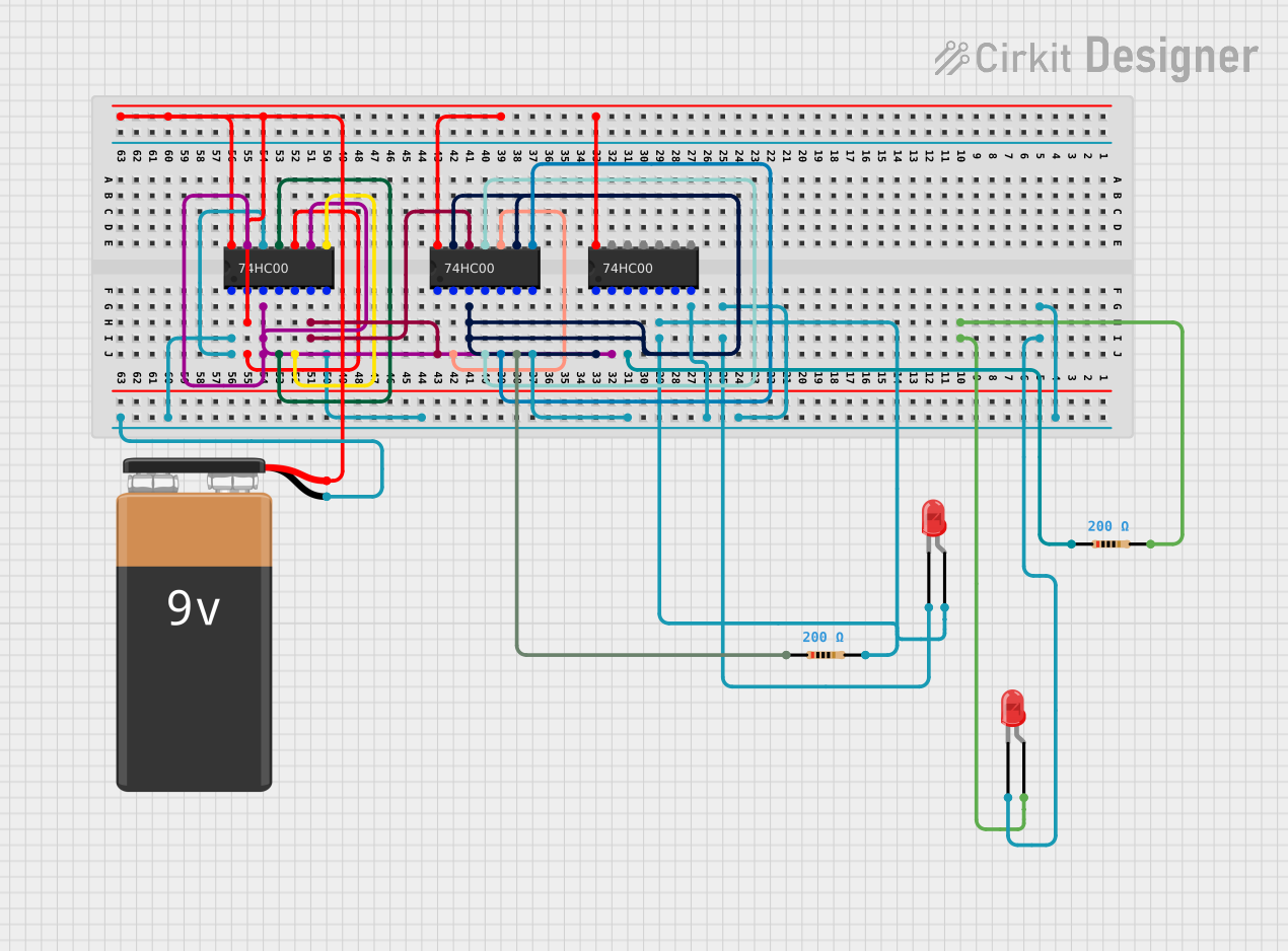
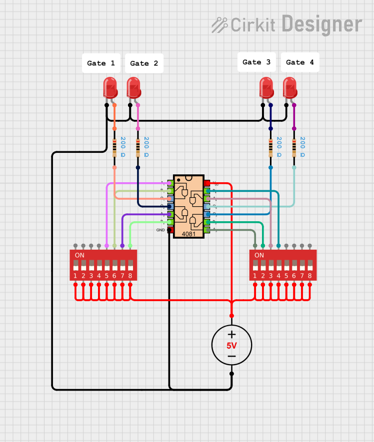
Explore Projects Built with Quad 2-Input NAND
Common Applications
- Logic function implementation in digital circuits
- Signal inversion and control
- Clock signal generation and gating
- Flip-flop and latch circuits
- General-purpose logic operations in microcontroller-based systems
Technical Specifications
The following table outlines the key technical details of the 7400 Quad 2-Input NAND Gate:
| Parameter | Value |
|---|---|
| Supply Voltage (Vcc) | 4.75V to 5.25V (typical 5V) |
| Input Voltage (VI) | 0V to Vcc |
| High-Level Output Voltage | 2.4V (minimum) |
| Low-Level Output Voltage | 0.4V (maximum) |
| High-Level Input Current | 40 µA (maximum) |
| Low-Level Input Current | -1.6 mA (maximum) |
| Propagation Delay (typical) | 10 ns |
| Power Dissipation | 10 mW (typical) |
| Operating Temperature Range | 0°C to 70°C |
| Package Type | DIP-14, SOIC-14, or other variants |
Pin Configuration and Descriptions
The 7400 is typically available in a 14-pin Dual Inline Package (DIP). The pinout and descriptions are as follows:
| Pin Number | Pin Name | Description |
|---|---|---|
| 1 | 1A | Input A for Gate 1 |
| 2 | 1B | Input B for Gate 1 |
| 3 | 1Y | Output of Gate 1 |
| 4 | 2A | Input A for Gate 2 |
| 5 | 2B | Input B for Gate 2 |
| 6 | 2Y | Output of Gate 2 |
| 7 | GND | Ground (0V) |
| 8 | 3Y | Output of Gate 3 |
| 9 | 3A | Input A for Gate 3 |
| 10 | 3B | Input B for Gate 3 |
| 11 | 4Y | Output of Gate 4 |
| 12 | 4A | Input A for Gate 4 |
| 13 | 4B | Input B for Gate 4 |
| 14 | Vcc | Positive Supply Voltage |
Usage Instructions
How to Use the 7400 in a Circuit
- Power Supply: Connect the Vcc pin (Pin 14) to a 5V DC power supply and the GND pin (Pin 7) to ground.
- Inputs: Provide logic-level inputs (0V for LOW, 5V for HIGH) to the input pins (e.g., 1A, 1B, etc.).
- Outputs: The output pins (e.g., 1Y, 2Y, etc.) will provide the NAND logic result based on the inputs.
- If both inputs are HIGH, the output will be LOW.
- For all other input combinations, the output will be HIGH.
- Load Considerations: Ensure the output current does not exceed the maximum rating to avoid damage.
Example Circuit
Below is an example of connecting a single NAND gate (Gate 1) from the 7400 to an LED:
- Connections:
- Connect Pin 1 (1A) and Pin 2 (1B) to two switches.
- Connect Pin 3 (1Y) to the anode of an LED through a 330Ω resistor.
- Connect the cathode of the LED to GND.
- Connect Pin 14 to 5V and Pin 7 to GND.
When both switches are closed (HIGH), the LED will turn off. For all other switch combinations, the LED will light up.
Arduino Example Code
The 7400 can be interfaced with an Arduino UNO to demonstrate its functionality. Below is an example code snippet:
// Define input and output pins
const int inputA = 2;  // Connect to 1A (Pin 1 of 7400)
const int inputB = 3;  // Connect to 1B (Pin 2 of 7400)
const int outputY = 4; // Connect to 1Y (Pin 3 of 7400)

void setup() {
  // Set input pins as outputs for Arduino
  pinMode(inputA, OUTPUT);
  pinMode(inputB, OUTPUT);

  // Set output pin as input for Arduino
  pinMode(outputY, INPUT);

  // Initialize Serial Monitor
  Serial.begin(9600);
}

void loop() {
  // Test all input combinations
  for (int a = 0; a <= 1; a++) {
    for (int b = 0; b <= 1; b++) {
      digitalWrite(inputA, a); // Set input A
      digitalWrite(inputB, b); // Set input B

      // Read the output of the NAND gate
      int output = digitalRead(outputY);

      // Print the results to the Serial Monitor
      Serial.print("Input A: ");
      Serial.print(a);
      Serial.print(", Input B: ");
      Serial.print(b);
      Serial.print(" -> Output Y: ");
      Serial.println(output);

      delay(1000); // Wait 1 second before next test
    }
  }
}
Important Considerations
- Unused Inputs: Always connect unused inputs to either HIGH or LOW to avoid floating states, which can cause unpredictable behavior.
- Power Supply: Ensure a stable 5V power supply to avoid erratic operation.
- Decoupling Capacitor: Place a 0.1 µF ceramic capacitor close to the Vcc and GND pins to filter noise.
Troubleshooting and FAQs
Common Issues
No Output Signal:
- Verify that the power supply is correctly connected to the Vcc and GND pins.
- Check for loose or incorrect wiring of the input and output connections.
Incorrect Logic Output:
- Ensure that the input signals are within the specified voltage range (0V to 5V).
- Check for floating inputs and connect them to a defined logic level.
Overheating:
- Verify that the output current does not exceed the maximum rating.
- Check for short circuits in the wiring.
FAQs
Q1: Can the 7400 operate at voltages other than 5V?
A1: The 7400 is designed for a typical 5V supply. Operating outside the recommended range (4.75V to 5.25V) may result in unreliable performance.
Q2: How many gates can I use simultaneously?
A2: All four gates in the 7400 can be used simultaneously, provided the total power dissipation does not exceed the specified limits.
Q3: Can I use the 7400 with a 3.3V microcontroller?
A3: The 7400 is not directly compatible with 3.3V logic levels. Use a level shifter or a 3.3V-compatible NAND gate instead.
By following this documentation, you can effectively integrate the 7400 Quad 2-Input NAND Gate into your digital circuit designs.