How to Use wt32-eth01: Examples, Pinouts, and Specs
Introduction
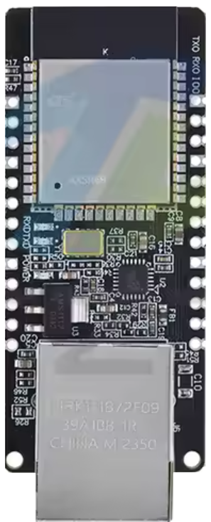
The WT32-ETH01 is a versatile Wi-Fi and Ethernet module that integrates the powerful ESP32 microcontroller with Ethernet capabilities. This module is designed to provide flexible connectivity options, supporting both wireless (Wi-Fi) and wired (Ethernet) communication. Its compact design and robust features make it ideal for a wide range of IoT applications, including smart home devices, industrial automation, and networked sensors.
Explore Projects Built with wt32-eth01

Explore Projects Built with wt32-eth01
Common Applications and Use Cases
- IoT devices requiring dual connectivity (Wi-Fi and Ethernet)
- Smart home automation systems
- Industrial control and monitoring
- Networked sensors and data loggers
- Remote device management and firmware updates
Technical Specifications
Key Technical Details
- Microcontroller: ESP32 (dual-core, 32-bit, Xtensa LX6)
- Wi-Fi: IEEE 802.11 b/g/n (2.4 GHz)
- Ethernet: 10/100 Mbps via LAN8720A PHY
- Flash Memory: 4 MB
- Operating Voltage: 3.3V
- Power Consumption: ~200 mA (Wi-Fi active)
- GPIO Pins: Configurable via ESP32
- Communication Interfaces: UART, SPI, I2C, PWM, ADC, DAC
- Dimensions: 50 mm x 25 mm
Pin Configuration and Descriptions
The WT32-ETH01 module has a 2x10 pin header. Below is the pinout and description:
| Pin | Name | Description |
|---|---|---|
| 1 | 3V3 | 3.3V power input |
| 2 | GND | Ground |
| 3 | TXD0 | UART0 Transmit (for serial communication) |
| 4 | RXD0 | UART0 Receive (for serial communication) |
| 5 | IO0 | GPIO0 (used for boot mode selection during programming) |
| 6 | IO2 | GPIO2 (general-purpose I/O) |
| 7 | IO4 | GPIO4 (general-purpose I/O) |
| 8 | IO5 | GPIO5 (general-purpose I/O) |
| 9 | IO12 | GPIO12 (general-purpose I/O) |
| 10 | IO13 | GPIO13 (general-purpose I/O) |
| 11 | IO14 | GPIO14 (general-purpose I/O) |
| 12 | IO15 | GPIO15 (general-purpose I/O) |
| 13 | IO16 | GPIO16 (general-purpose I/O) |
| 14 | IO17 | GPIO17 (general-purpose I/O) |
| 15 | EN | Enable pin (active high, used to reset the module) |
| 16 | ETH_TXD0 | Ethernet Transmit Data 0 |
| 17 | ETH_TXD1 | Ethernet Transmit Data 1 |
| 18 | ETH_RXD0 | Ethernet Receive Data 0 |
| 19 | ETH_RXD1 | Ethernet Receive Data 1 |
| 20 | ETH_CLK | Ethernet Clock (50 MHz) |
Usage Instructions
How to Use the WT32-ETH01 in a Circuit
- Power Supply: Provide a stable 3.3V power supply to the
3V3pin and connectGNDto ground. - Programming: Use the UART0 pins (
TXD0andRXD0) to program the ESP32 microcontroller. GPIO0 (IO0) should be pulled low during programming to enter boot mode. - Ethernet Connection: Connect the Ethernet cable to the RJ45 port on the module. The Ethernet pins (
ETH_TXD0,ETH_TXD1,ETH_RXD0,ETH_RXD1, andETH_CLK) are internally connected to the LAN8720A PHY. - Wi-Fi Configuration: Configure the Wi-Fi settings in your firmware to enable wireless communication.
- GPIO Usage: Use the available GPIO pins for interfacing with sensors, actuators, or other peripherals.
Important Considerations and Best Practices
- Ensure the power supply is clean and stable to avoid unexpected resets or malfunctions.
- Use level shifters if interfacing with 5V logic devices, as the WT32-ETH01 operates at 3.3V logic levels.
- When using Ethernet, ensure the RJ45 connector is properly grounded to reduce noise and improve signal integrity.
- Avoid using GPIO0, GPIO2, and GPIO15 for general-purpose I/O if they are needed for boot or programming modes.
Example Code for Arduino UNO
The WT32-ETH01 can be programmed using the Arduino IDE. Below is an example of how to configure the module for Ethernet communication:
#include <ETH.h> // Include the Ethernet library for ESP32

// Define Ethernet configuration
#define ETH_CLK_MODE ETH_CLOCK_GPIO0_IN // Use GPIO0 for Ethernet clock
#define ETH_PHY_POWER 12               // GPIO12 controls Ethernet PHY power

void setup() {
  Serial.begin(115200); // Initialize serial communication
  Serial.println("Initializing Ethernet...");

  // Initialize Ethernet with default settings
  if (!ETH.begin(ETH_PHY_POWER, ETH_CLK_MODE)) {
    Serial.println("Ethernet initialization failed!");
    while (1); // Halt execution if Ethernet fails to initialize
  }

  Serial.println("Ethernet initialized successfully!");
  Serial.print("IP Address: ");
  Serial.println(ETH.localIP()); // Print the assigned IP address
}

void loop() {
  // Main loop can handle other tasks or network communication
}
Troubleshooting and FAQs
Common Issues and Solutions
Ethernet Not Working:
- Ensure the Ethernet cable is securely connected to the RJ45 port.
- Verify that the Ethernet PHY power pin (default GPIO12) is properly configured in your code.
- Check the network settings (e.g., DHCP or static IP configuration).
Wi-Fi Connection Fails:
- Double-check the SSID and password in your firmware.
- Ensure the module is within range of the Wi-Fi router.
- Verify that the Wi-Fi antenna is properly connected (if external).
Module Not Responding:
- Confirm that the power supply is providing a stable 3.3V.
- Check the UART connections and ensure the correct baud rate is set in your serial monitor.
- If programming fails, ensure GPIO0 is pulled low during the boot process.
FAQs
Can I use both Wi-Fi and Ethernet simultaneously? Yes, the WT32-ETH01 supports simultaneous use of Wi-Fi and Ethernet, but you may need to manage the network interfaces in your firmware.
What is the maximum data rate for Ethernet? The module supports up to 100 Mbps Ethernet communication.
Can I power the module with 5V? No, the WT32-ETH01 requires a 3.3V power supply. Use a voltage regulator if your power source is 5V.
Is the module compatible with Arduino IDE? Yes, the WT32-ETH01 can be programmed using the Arduino IDE with the appropriate ESP32 board package installed.