How to Use A4988 on Breakout Board: Examples, Pinouts, and Specs
Introduction
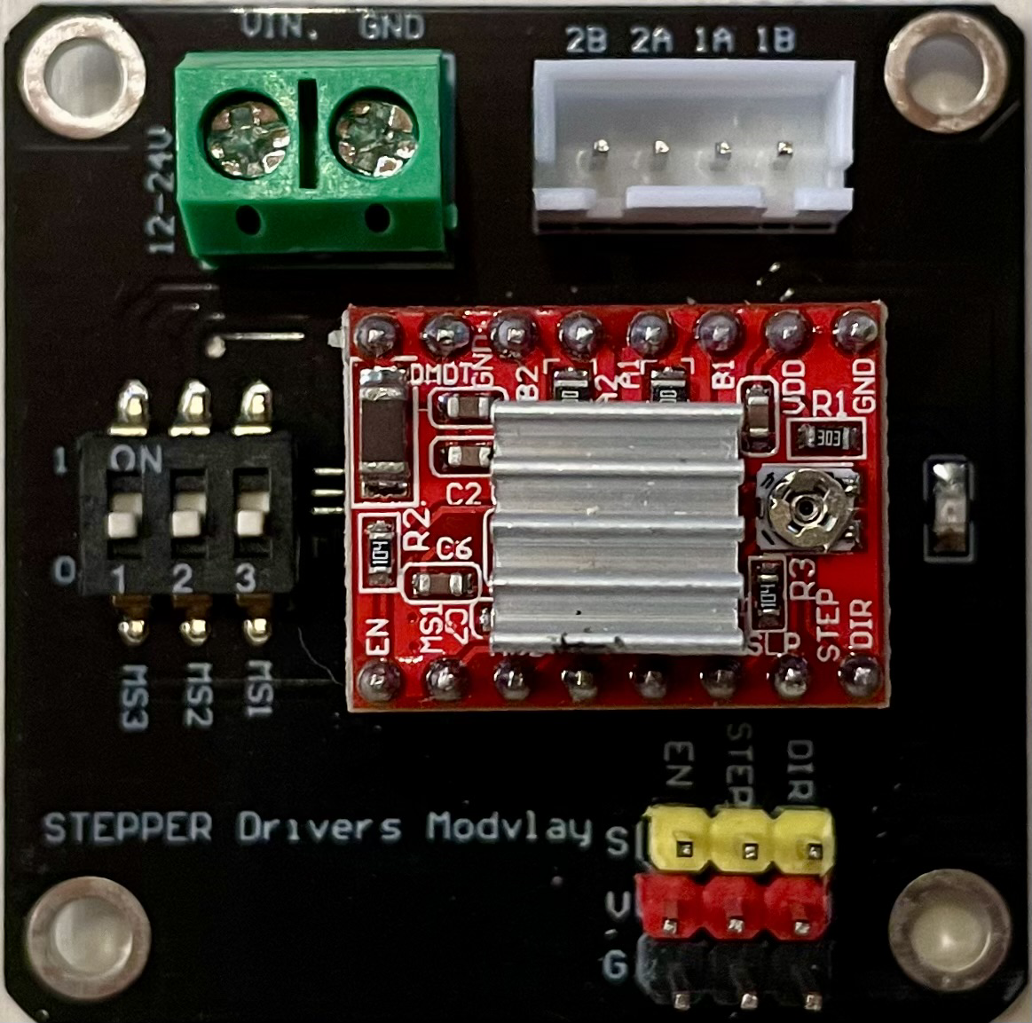
The A4988 stepper motor driver on a breakout board is a compact, complete microstepping motor driver with a built-in translator for easy operation. It is designed to operate bipolar stepper motors in full-, half-, quarter-, eighth-, and sixteenth-step modes, with an output drive capacity of up to 35 V and ±2 A. The A4988 is commonly used in 3D printers, CNC machines, and other applications where precise control of a stepper motor is required.
Explore Projects Built with A4988 on Breakout Board


Explore Projects Built with A4988 on Breakout Board
Technical Specifications
Key Technical Details
- Logic Voltage (VDD): 3.3 - 5.5 V
- Motor Supply Voltage (VM): 8 - 35 V
- Output Current: 1 A per phase without a heat sink or forced air flow (up to 2 A with sufficient additional cooling)
- Five Step Resolutions: Full-step, Half-step, Quarter-step, Eighth-step, and Sixteenth-step
- Adjustable Current Control: Potentiometer to set the maximum current output
- Over-Temperature Thermal Shutdown
- Under-Voltage Lockout
- Crossover-Current Protection
Pin Configuration and Descriptions
| Pin Number | Name | Description |
|---|---|---|
| 1 | VMOT | Motor supply voltage (8 - 35 V) |
| 2 | GND | Ground (0 V) |
| 3 | 2B | Motor connection B |
| 4 | 2A | Motor connection A |
| 5 | 1A | Motor connection A |
| 6 | 1B | Motor connection B |
| 7 | VDD | Logic supply voltage (3.3 - 5.5 V) |
| 8 | GND | Ground (0 V) |
| 9 | STEP | Step input (pulses) |
| 10 | DIR | Direction input |
| 11 | MS1 | Microstep selection 1 |
| 12 | MS2 | Microstep selection 2 |
| 13 | MS3 | Microstep selection 3 |
| 14 | RESET | Resets the driver when pulled low |
| 15 | SLEEP | Puts the driver in sleep mode when pulled low |
| 16 | EN | Enables the driver when pulled low |
Usage Instructions
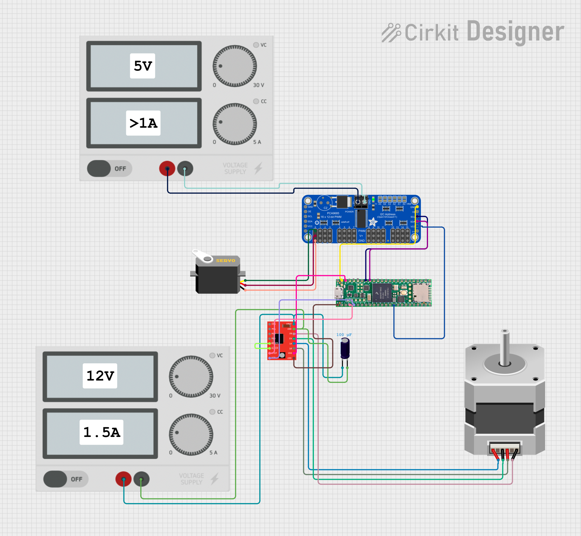
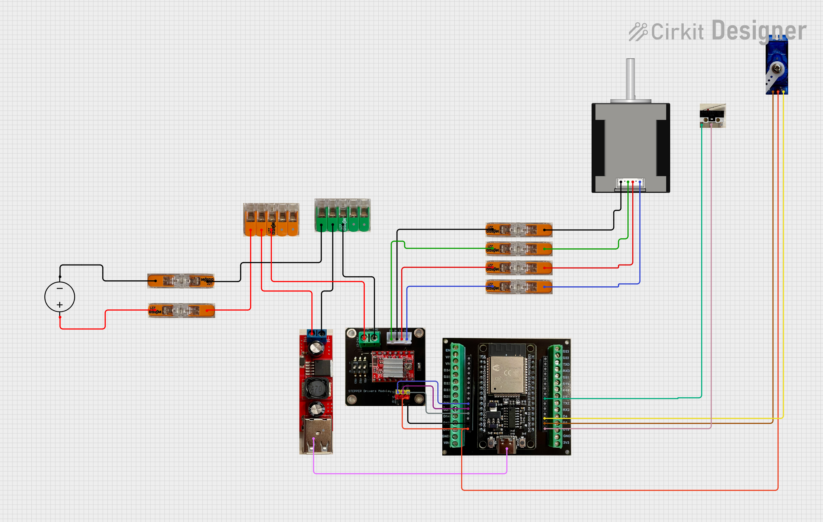
Connecting the A4988 to a Circuit
- Connect VMOT (Pin 1) to your motor power supply (8 - 35 V).
- Connect the two motor wires to 1A (Pin 5) and 1B (Pin 6), and the other two wires to 2A (Pin 4) and 2B (Pin 3).
- Connect VDD (Pin 7) to a 3.3 - 5.5 V logic supply.
- Connect the STEP (Pin 9) and DIR (Pin 10) to the control signals (usually from a microcontroller).
- Set the current limit using the onboard potentiometer.
- Use the MS1 (Pin 11), MS2 (Pin 12), and MS3 (Pin 13) pins to set the desired microstepping resolution.
Important Considerations and Best Practices
- Always ensure the power supply is off when connecting or disconnecting the motor to prevent damage to the A4988.
- Adjust the current limiting potentiometer carefully to prevent overcurrent which can damage the motor or the A4988.
- Use a heat sink if the current exceeds 1 A per phase.
- Provide adequate ventilation to prevent overheating.
- Connect a suitable decoupling capacitor (typically 100 µF) across VMOT and GND to protect against voltage spikes.
Example Code for Arduino UNO
// Define step and direction pins
#define DIR_PIN 2
#define STEP_PIN 3

void setup() {
  // Set the motor control pins as outputs
  pinMode(DIR_PIN, OUTPUT);
  pinMode(STEP_PIN, OUTPUT);
}

void loop() {
  // Set the direction
  digitalWrite(DIR_PIN, HIGH); // Set to LOW to change direction

  // Move the motor with a simple stepping pattern
  for (int i = 0; i < 200; i++) {
    // Pulse the STEP pin to move the motor
    digitalWrite(STEP_PIN, HIGH);
    delayMicroseconds(800); // Adjust the speed
    digitalWrite(STEP_PIN, LOW);
    delayMicroseconds(800); // Adjust the speed
  }

  // Pause before changing direction
  delay(1000);
}
Troubleshooting and FAQs
Common Issues
- Motor not moving: Check connections, ensure power supply is adequate, and verify that the current limit is properly set.
- Motor getting hot: Reduce the current limit, check for proper microstepping settings, and ensure the motor is not stalled or overloaded.
- Erratic motor behavior: Ensure there is no electrical noise affecting the STEP or DIR signals, and that the power supply is stable.
Solutions and Tips for Troubleshooting
- Double-check wiring, especially the motor coil connections to the A4988.
- Use a multimeter to verify the voltage at VMOT and VDD.
- If the motor vibrates but does not turn, try reducing the stepping speed or increasing the current limit slightly.
- Ensure that the logic signals (STEP and DIR) have clean transitions without bounce.
FAQs
Q: Can I drive a motor that requires more than 2 A with the A4988? A: No, the A4988 is limited to 2 A per phase with proper cooling. For higher currents, consider using a driver capable of handling the required current.
Q: How do I set the current limit on the A4988? A: Turn the potentiometer while measuring the voltage on the REF pin or the VREF voltage at the potentiometer. Use the formula provided in the datasheet to calculate the appropriate VREF for your motor's current limit.
Q: What is the purpose of the microstep pins (MS1, MS2, MS3)? A: These pins allow you to select the microstepping resolution. By setting these pins HIGH or LOW, you can choose between full-step, half-step, quarter-step, eighth-step, and sixteenth-step modes.
Q: Why does my motor make a whining noise? A: This can be due to high current settings or rapid stepping. Try adjusting the current limit or step rate. Additionally, microstepping can reduce noise and provide smoother motion.