A kontaktor is an electromechanical switch designed to control high-power circuits using low-power signals. Manufactured by Schneider, the High Volt kontaktor is a reliable and robust solution for industrial applications. It is commonly used to switch electrical loads such as motors, lighting systems, heating elements, and other high-power devices. Its ability to handle high currents and voltages makes it an essential component in automation and power distribution systems.
Explore Projects Built with Kontaktor
Use Cirkit Designer to design, explore, and prototype these projects online. Some projects support real-time simulation. Click "Open Project" to start designing instantly!
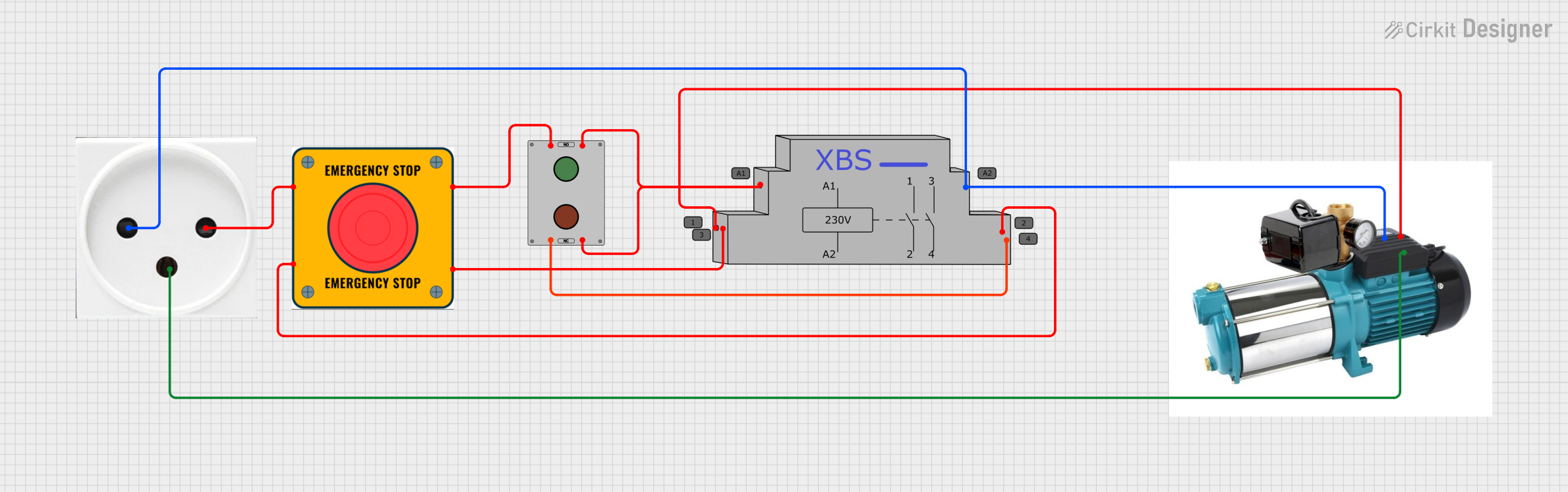
This circuit is designed to control a pump using a contactor that is manually operated by a switch and can be overridden by an emergency stop. The contactor enables power from an AC power outlet to the pump, and the emergency stop can interrupt the power circuit for safety purposes.
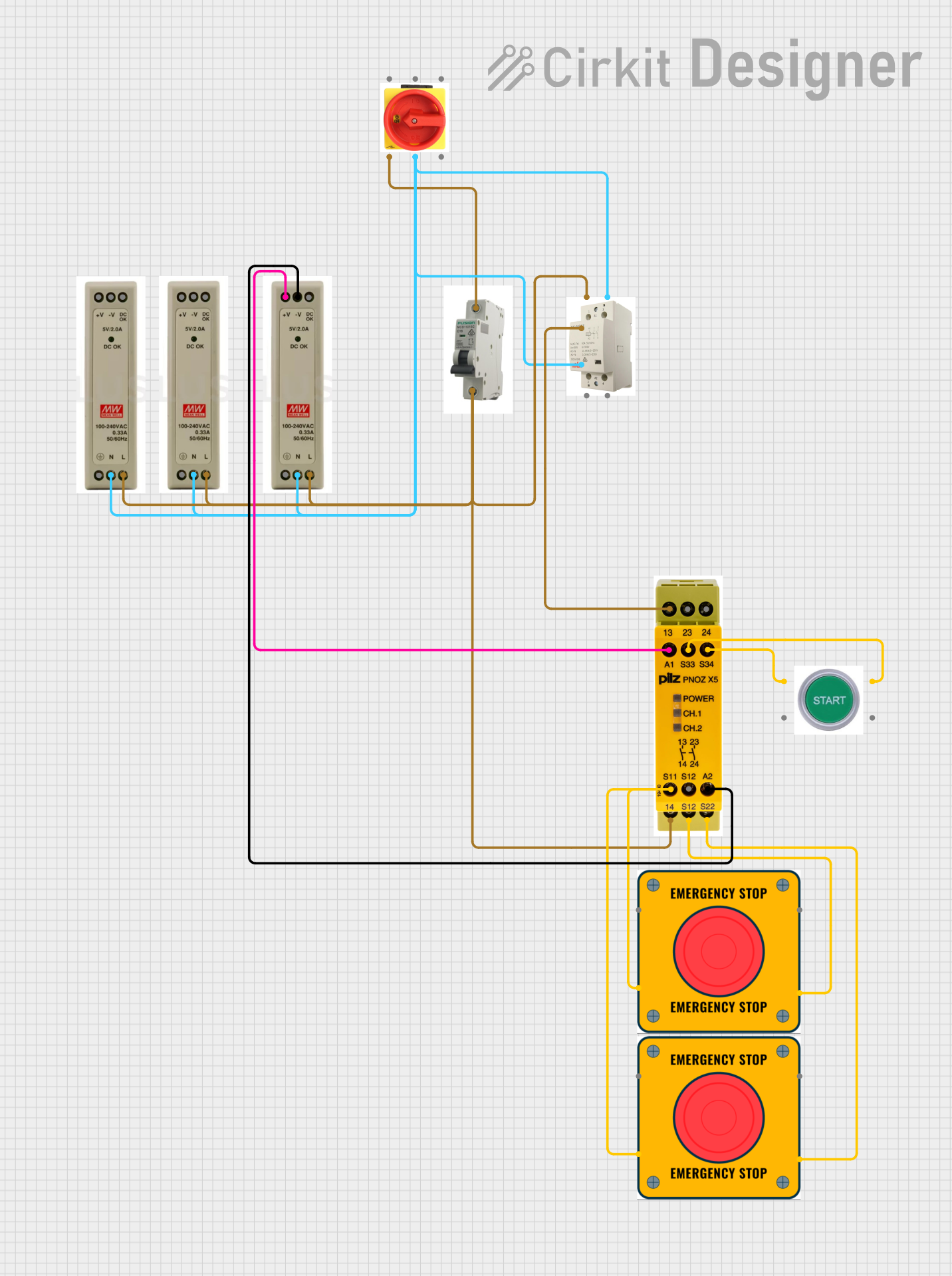
This circuit is designed for power distribution and safety control in an industrial setting. It features a main isolator and circuit breaker for power management, multiple PSUs for 5V, 12V, and 24V outputs, and a safety relay system that interfaces with E-stop buttons and a start switch to control a main contactor, ensuring safe operation and emergency power cut-off capabilities.
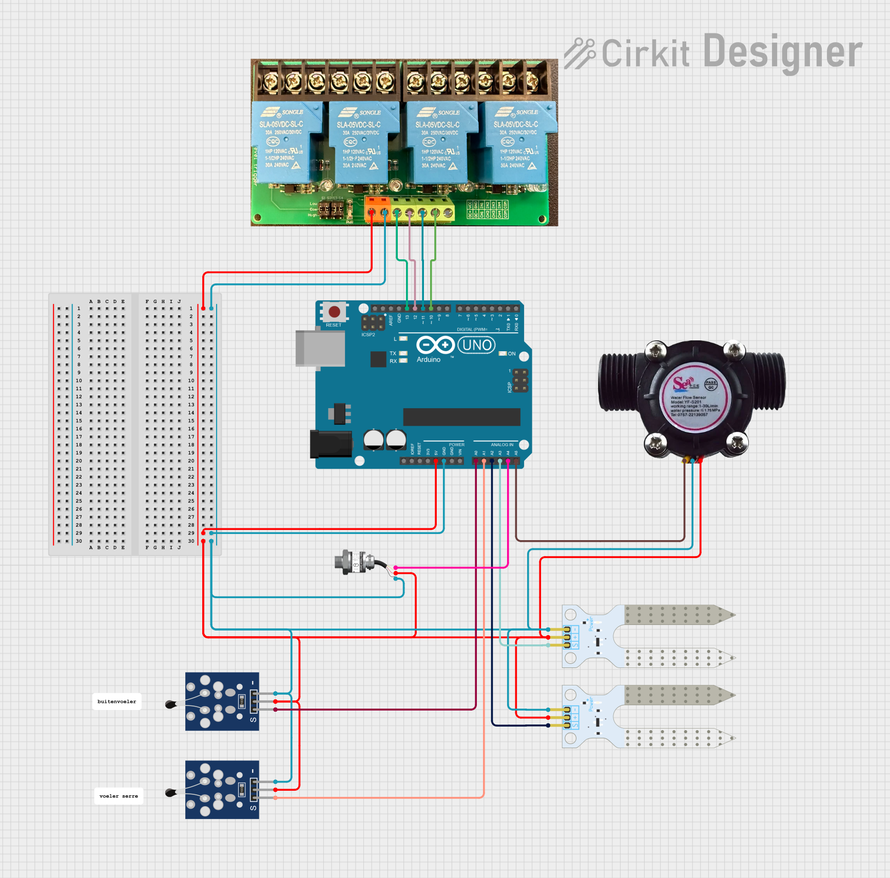
This circuit uses an Arduino UNO to monitor environmental conditions through various sensors, including soil moisture sensors, temperature sensors, a water flow sensor, and a fluid pressure sensor. The Arduino also controls a 4-channel relay module, which can be used to actuate external devices based on sensor readings.
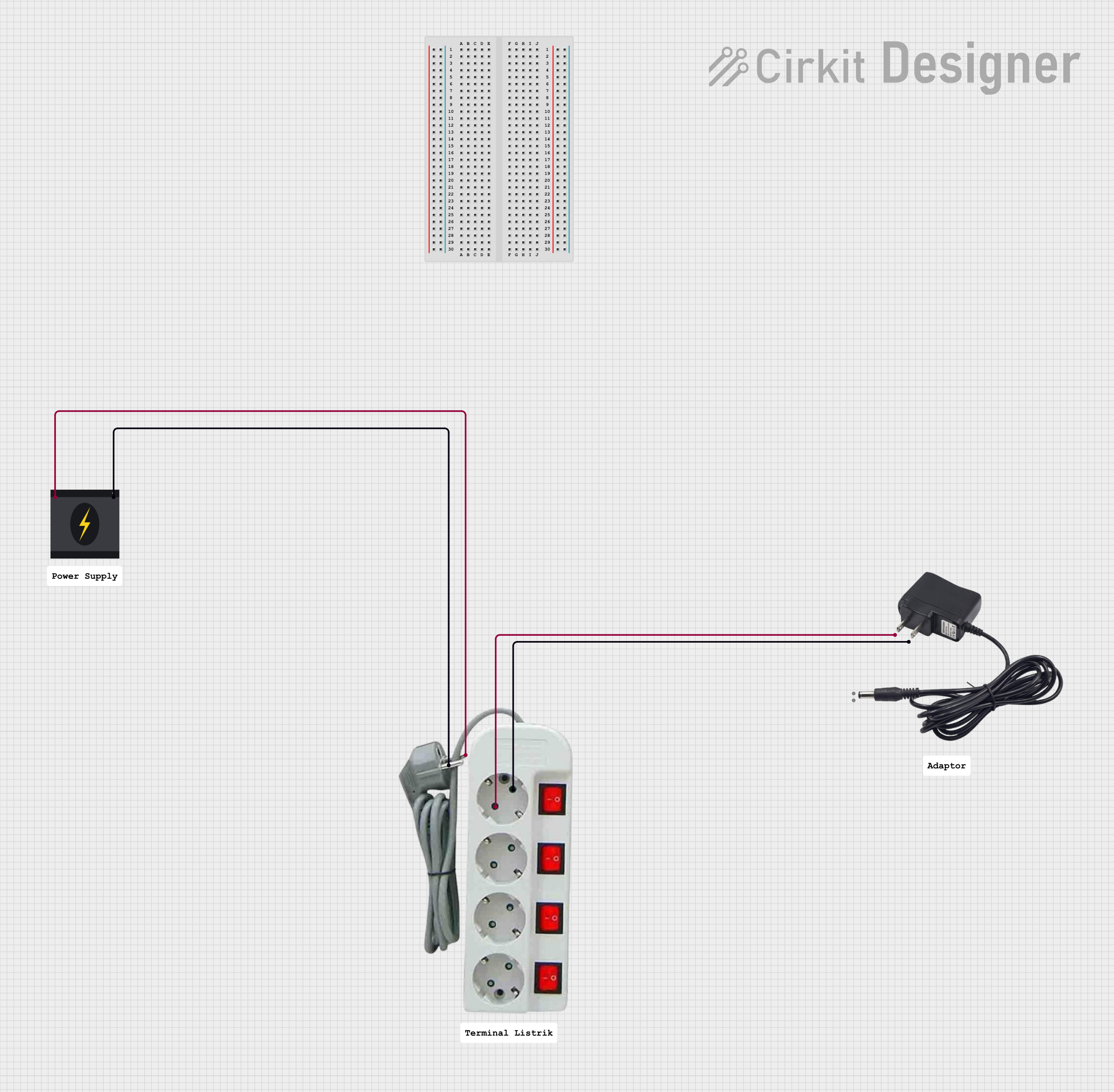
This circuit converts a 240V AC power source to a 12V DC output using a 12V adapter. The 240V AC power source is connected to a stopkontak, which then supplies the 12V adapter with the necessary AC voltage to produce a 12V DC output.
Lighting control in commercial and industrial buildings
Heating, ventilation, and air conditioning (HVAC) systems
Power distribution and automation systems
Renewable energy systems (e.g., solar inverters)
Technical Specifications
Key Specifications
Parameter
Value
Manufacturer
Schneider
Part ID
High Volt
Rated Operating Voltage
24V DC (coil), 690V AC (load)
Rated Current
40A
Number of Poles
3P (Three Poles)
Coil Power Consumption
8W
Mechanical Durability
10 million operations
Electrical Durability
1 million operations
Operating Temperature
-25°C to +60°C
Mounting Type
DIN Rail or Panel Mount
Pin Configuration and Descriptions
The High Volt kontaktor has the following terminal layout:
Power Terminals
Terminal Label
Description
L1, L2, L3
Input terminals for three-phase AC
T1, T2, T3
Output terminals for three-phase AC
Control Terminals
Terminal Label
Description
A1
Positive terminal for the coil
A2
Negative terminal for the coil
Auxiliary Contacts (Optional)
Terminal Label
Description
NO (Normally Open)
Auxiliary contact for control circuits
NC (Normally Closed)
Auxiliary contact for control circuits
Usage Instructions
How to Use the Kontaktor in a Circuit
Power Connections:
Connect the three-phase AC input to the terminals L1, L2, L3.
Connect the load (e.g., motor, lighting) to the output terminals T1, T2, T3.
Control Circuit:
Connect the control voltage (e.g., 24V DC) to the coil terminals A1 and A2.
Ensure the control circuit includes a switch or relay to activate the coil.
Auxiliary Contacts (if applicable):
Use the auxiliary contacts (NO/NC) for feedback or interlocking in control circuits.
Mounting:
Secure the kontaktor on a DIN rail or panel using the provided mounting options.
Important Considerations
Voltage and Current Ratings: Ensure the load does not exceed the rated voltage (690V AC) or current (40A).
Coil Voltage: Verify that the control voltage matches the coil's rated voltage (24V DC).
Overload Protection: Use appropriate overload relays or circuit breakers to protect the circuit.
Wiring: Use wires with adequate gauge to handle the current and voltage safely.
Environment: Install the kontaktor in a clean, dry environment within the specified temperature range (-25°C to +60°C).
Example: Connecting to an Arduino UNO
The High Volt kontaktor can be controlled using an Arduino UNO and a relay module. Below is an example circuit and code:
Circuit Description
The Arduino controls a relay module, which in turn activates the kontaktor's coil.
The relay module isolates the Arduino from the high-power circuit.
Arduino Code
// Define the relay control pin
const int relayPin = 7;

void setup() {
  pinMode(relayPin, OUTPUT); // Set the relay pin as an output
  digitalWrite(relayPin, LOW); // Ensure the relay is off initially
}

void loop() {
  // Turn on the relay (activates the kontaktor)
  digitalWrite(relayPin, HIGH);
  delay(5000); // Keep the relay on for 5 seconds

  // Turn off the relay (deactivates the kontaktor)
  digitalWrite(relayPin, LOW);
  delay(5000); // Keep the relay off for 5 seconds
}
Note: Ensure the relay module is rated for 24V DC to match the coil voltage of the kontaktor.
Troubleshooting and FAQs
Common Issues and Solutions
Kontaktor Does Not Activate:
Cause: No control voltage or incorrect wiring.
Solution: Verify the control voltage at terminals A1 and A2. Check the wiring and ensure the control circuit is functional.
Excessive Heating:
Cause: Overloaded circuit or poor ventilation.
Solution: Ensure the load does not exceed the rated current (40A). Install the kontaktor in a well-ventilated area.
Chattering Noise:
Cause: Insufficient or unstable control voltage.
Solution: Check the control voltage and ensure it is stable and within the specified range (24V DC).
Auxiliary Contacts Not Working:
Cause: Incorrect wiring or damaged contacts.
Solution: Verify the wiring of the auxiliary contacts. Replace the contacts if damaged.
FAQs
Q: Can the kontaktor handle single-phase loads?
A: Yes, connect the single-phase load to one of the poles (e.g., L1 and T1).
Q: Is the kontaktor suitable for outdoor use?
A: The High Volt kontaktor is not weatherproof. Use it in a protected enclosure for outdoor applications.
Q: Can I use the kontaktor with a 12V DC control voltage?
A: No, the coil is rated for 24V DC. Using a lower voltage may result in unreliable operation.
Q: How do I test the kontaktor?
A: Apply the rated control voltage (24V DC) to the coil terminals A1 and A2. The main contacts should close, and you should hear a clicking sound.
This concludes the documentation for the Schneider High Volt Kontaktor. For further assistance, refer to the manufacturer's datasheet or contact technical support.


 Open Project in Cirkit Designer