Cirkit Designer Logo
Cirkit Designer
Your all-in-one circuit design IDE
Home / 
Component Documentation

How to Use MCP7384XX: Examples, Pinouts, and Specs

Image of MCP7384XX
Cirkit Designer LogoDesign with MCP7384XX in Cirkit Designer

Introduction

The MCP7384XX is a sophisticated linear charge management controller designed for applications where space is at a premium and cost-effectiveness is crucial. It is ideal for single-cell, lithium-ion (Li-ion), or lithium-polymer (Li-Poly) battery charging. This component is commonly used in portable electronics, such as smartphones, tablets, and wearable devices, due to its compact size and efficiency.

Explore Projects Built with MCP7384XX

Use Cirkit Designer to design, explore, and prototype these projects online. Some projects support real-time simulation. Click "Open Project" to start designing instantly!
Wi-Fi Controlled Relay Module with ESP8266 and MCP23017
Image of smart home: A project utilizing MCP7384XX in a practical application
This circuit is a WiFi-enabled relay control system using an ESP8266-01 module and an MCP23017 I/O expander. The ESP8266 communicates with the MCP23017 via I2C to control an 8-channel relay module based on the state of 8 rocker switches, allowing for remote and manual control of connected devices.
Cirkit Designer LogoOpen Project in Cirkit Designer
ESP32-Based I2C Communication Hub with Multiplexer and Expander
Image of Lights: A project utilizing MCP7384XX in a practical application
This circuit features an Olimex ESP32-EVB microcontroller unit (MCU) for processing and connectivity, interfaced with an MCP23017 I/O expander and an Adafruit TCA9548A I2C multiplexer to expand the number of I/O lines and allow multiple I2C devices to communicate with the MCU over the same bus. Pull-up resistors are connected to the I2C lines for proper bus operation, and both the MCP23017 and TCA9548A have their reset lines pulled high, likely for normal operation without external reset control.
Cirkit Designer LogoOpen Project in Cirkit Designer
Wi-Fi Controlled Smart Relay Switch with ESP8266 and MCP23017
Image of Bed Room: A project utilizing MCP7384XX in a practical application
This circuit is designed to control an 8-channel relay module via an ESP8266 microcontroller, which interfaces with an MCP23017 I/O expander over I2C. The ESP8266 connects to a WiFi network and subscribes to MQTT topics to receive commands for toggling the relays. Additionally, there are toggle switches connected to the MCP23017 that allow manual control of the relays, with the system's state being reported back via MQTT.
Cirkit Designer LogoOpen Project in Cirkit Designer
STM32 and ESP32 CAN Bus Communication System with MCP2515
Image of CAR HACKING: A project utilizing MCP7384XX in a practical application
This circuit integrates multiple microcontrollers (STM32F103C8T6, ESP32, and Raspberry Pi Pico W) with MCP2515 CAN controllers to facilitate CAN bus communication. The microcontrollers are connected to the MCP2515 modules via SPI interfaces, and the circuit includes USB-to-serial converters for programming and debugging purposes.
Cirkit Designer LogoOpen Project in Cirkit Designer

Explore Projects Built with MCP7384XX

Use Cirkit Designer to design, explore, and prototype these projects online. Some projects support real-time simulation. Click "Open Project" to start designing instantly!
Image of smart home: A project utilizing MCP7384XX in a practical application
Wi-Fi Controlled Relay Module with ESP8266 and MCP23017
This circuit is a WiFi-enabled relay control system using an ESP8266-01 module and an MCP23017 I/O expander. The ESP8266 communicates with the MCP23017 via I2C to control an 8-channel relay module based on the state of 8 rocker switches, allowing for remote and manual control of connected devices.
Cirkit Designer LogoOpen Project in Cirkit Designer
Image of Lights: A project utilizing MCP7384XX in a practical application
ESP32-Based I2C Communication Hub with Multiplexer and Expander
This circuit features an Olimex ESP32-EVB microcontroller unit (MCU) for processing and connectivity, interfaced with an MCP23017 I/O expander and an Adafruit TCA9548A I2C multiplexer to expand the number of I/O lines and allow multiple I2C devices to communicate with the MCU over the same bus. Pull-up resistors are connected to the I2C lines for proper bus operation, and both the MCP23017 and TCA9548A have their reset lines pulled high, likely for normal operation without external reset control.
Cirkit Designer LogoOpen Project in Cirkit Designer
Image of Bed Room: A project utilizing MCP7384XX in a practical application
Wi-Fi Controlled Smart Relay Switch with ESP8266 and MCP23017
This circuit is designed to control an 8-channel relay module via an ESP8266 microcontroller, which interfaces with an MCP23017 I/O expander over I2C. The ESP8266 connects to a WiFi network and subscribes to MQTT topics to receive commands for toggling the relays. Additionally, there are toggle switches connected to the MCP23017 that allow manual control of the relays, with the system's state being reported back via MQTT.
Cirkit Designer LogoOpen Project in Cirkit Designer
Image of CAR HACKING: A project utilizing MCP7384XX in a practical application
STM32 and ESP32 CAN Bus Communication System with MCP2515
This circuit integrates multiple microcontrollers (STM32F103C8T6, ESP32, and Raspberry Pi Pico W) with MCP2515 CAN controllers to facilitate CAN bus communication. The microcontrollers are connected to the MCP2515 modules via SPI interfaces, and the circuit includes USB-to-serial converters for programming and debugging purposes.
Cirkit Designer LogoOpen Project in Cirkit Designer

Technical Specifications

Key Technical Details

  • Battery Type: Li-ion/Li-Poly
  • Charge Regulation: Linear
  • Input Voltage Range: 4.5V to 6.0V
  • Programmable Charge Current: Up to 1A
  • Charge Voltage Accuracy: ±0.5%
  • Operating Temperature Range: -40°C to +85°C

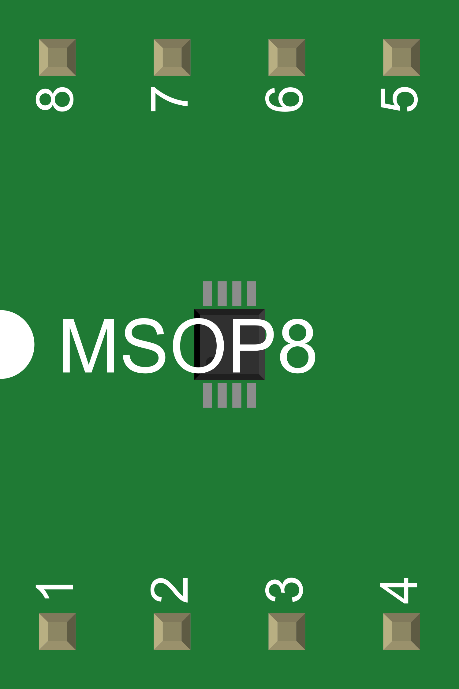
Pin Configuration and Descriptions

Pin Number Name Description
1 VDD Power supply input. Connect to a 4.5V to 6.0V source.
2 GND Ground reference for the circuit.
3 PROG Charge current programming pin. Connect a resistor to GND to set the charge current.
4 STAT1 Status output 1. Can be used to indicate charge status or faults.
5 STAT2 Status output 2. Can be used in conjunction with STAT1 for charge status indication.
6 THERM Temperature sense input. Connect to an NTC thermistor for temperature-based charge suspension.
7 VBAT Battery connection pin. Connect to the positive terminal of the battery.
8 CE Chip enable input. A low level enables the chip; a high level puts it into shutdown mode.
9 - Not connected.
10 - Not connected.

Usage Instructions

How to Use the MCP7384XX in a Circuit

  1. Power Supply Connection: Connect a stable 4.5V to 6.0V power supply to the VDD pin and connect the GND pin to the system ground.

  2. Setting Charge Current: Connect a resistor from the PROG pin to GND to set the desired charge current. The value of the resistor can be calculated based on the datasheet specifications.

  3. Battery Connection: Connect the positive terminal of the Li-ion/Li-Poly battery to the VBAT pin.

  4. Temperature Sensing: If temperature-based charge suspension is desired, connect an NTC thermistor to the THERM pin.

  5. Charge Enable: To enable charging, apply a low level to the CE pin. To disable or put the chip into shutdown mode, apply a high level.

  6. Status Indication: Connect STAT1 and STAT2 to LEDs or to a microcontroller to monitor the charge status.

Important Considerations and Best Practices

  • Ensure that the power supply voltage does not exceed the maximum input voltage rating.
  • Use a stable power source to avoid fluctuations that could affect the charging process.
  • Always verify the charge current setting by measuring the voltage across the PROG resistor and consulting the datasheet.
  • Implement proper thermal management to prevent overheating during charging.
  • Monitor the status outputs to ensure the battery is charging correctly and to detect any faults.

Troubleshooting and FAQs

Common Issues

  • Battery Not Charging: Ensure that the CE pin is enabled, the power supply is within the specified range, and the PROG resistor is correctly sized.
  • Overheating: Check for adequate ventilation around the MCP7384XX and confirm that the charge current is not set too high.
  • Inaccurate Charge Current: Double-check the value of the PROG resistor and ensure it is within tolerance.

Solutions and Tips

  • If the battery is not charging, verify the connections to the VBAT, VDD, and GND pins, and ensure the CE pin is low.
  • For overheating issues, consider adding a heatsink or improving airflow around the component.
  • Use precision resistors for setting the charge current to improve accuracy.

FAQs

Q: Can the MCP7384XX be used for charging multiple cells in series? A: No, the MCP7384XX is designed for single-cell Li-ion/Li-Poly batteries.

Q: What should I do if the STAT1 and STAT2 LEDs do not light up? A: Check the connections to the STAT pins and ensure that the LEDs are correctly oriented. Also, verify that the MCP7384XX is not in shutdown mode.

Q: How can I adjust the charge current? A: Change the value of the resistor connected to the PROG pin according to the formula provided in the datasheet.

Q: Is it necessary to use the THERM pin? A: While not mandatory, using the THERM pin with an NTC thermistor is recommended for safety, as it allows the MCP7384XX to suspend charging if the battery temperature is out of the safe range.

For any further assistance or detailed information, refer to the MCP7384XX datasheet or contact technical support.