How to Use General Driver Board for Robots: Examples, Pinouts, and Specs
Introduction
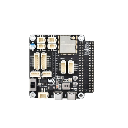
The General Driver Board for Robots (Manufacturer: Waveshare, Part ID: 23730) is a versatile circuit board designed to control the motors and sensors of a robot. It provides essential interfaces and power management for various robotic components, making it an ideal choice for hobbyists, students, and professionals working on robotic projects.
This driver board simplifies the integration of motors, sensors, and other peripherals into robotic systems. It supports multiple motor types, such as DC motors and stepper motors, and includes features like overcurrent protection and voltage regulation. The board is compatible with popular microcontrollers, including Arduino and Raspberry Pi, enabling seamless control and communication.
Explore Projects Built with General Driver Board for Robots
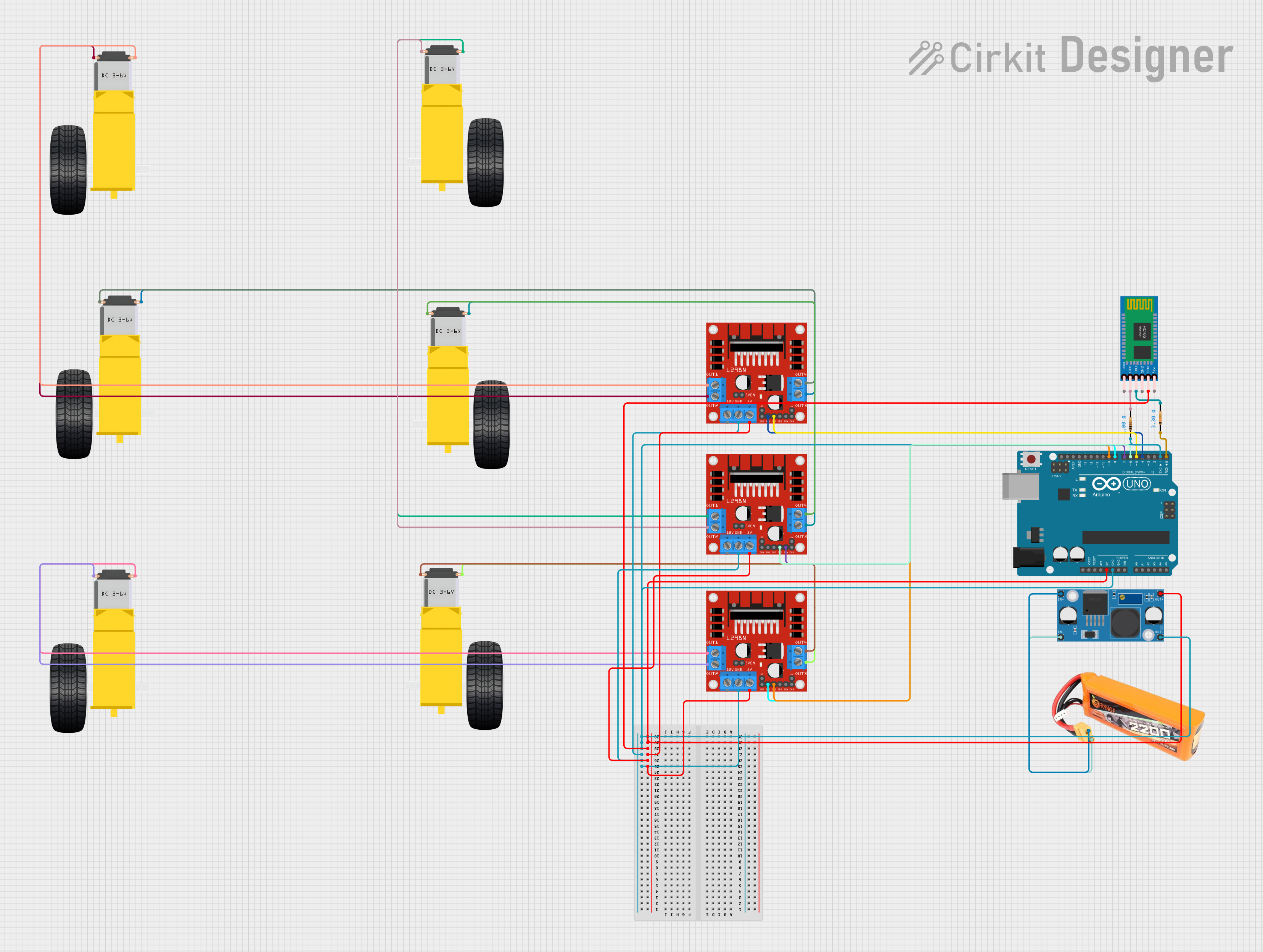
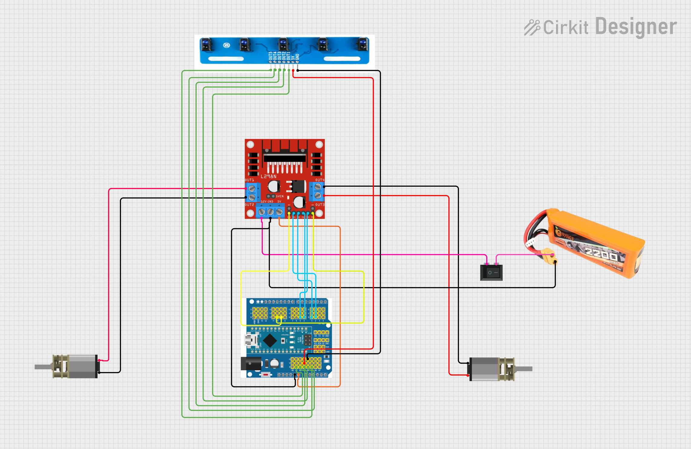

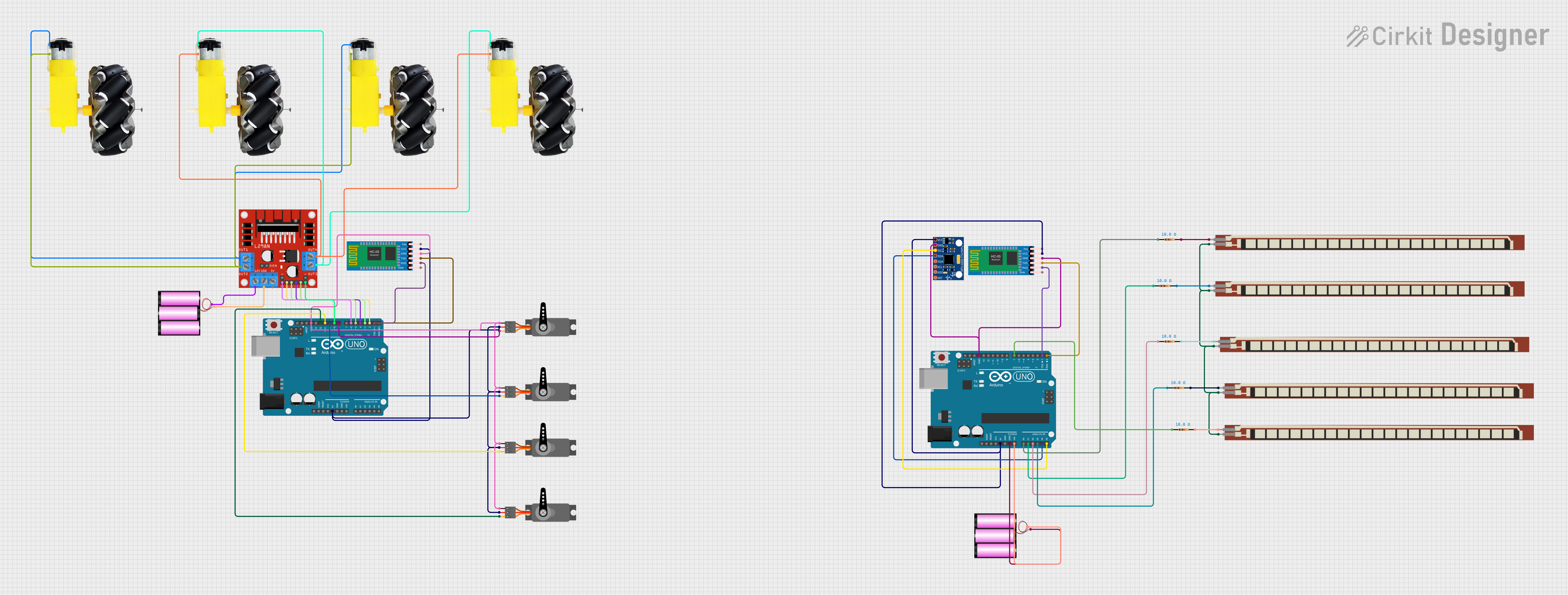
Explore Projects Built with General Driver Board for Robots
Common Applications and Use Cases
- Driving DC motors, stepper motors, and servo motors in robotic systems
- Powering and interfacing with sensors for autonomous robots
- Educational robotics projects and prototyping
- Industrial automation and robotic arms
- DIY robotic vehicles and drones
Technical Specifications
The following table outlines the key technical details of the General Driver Board for Robots:
| Specification | Details |
|---|---|
| Manufacturer | Waveshare |
| Part ID | 23730 |
| Input Voltage Range | 6V to 12V |
| Motor Driver IC | L298N Dual H-Bridge Motor Driver |
| Maximum Motor Current | 2A per channel |
| Number of Motor Channels | 2 (supports two DC motors or one stepper motor) |
| Logic Voltage | 5V |
| Communication Interface | GPIO (compatible with Arduino, Raspberry Pi, etc.) |
| Protection Features | Overcurrent protection, thermal shutdown |
| Dimensions | 60mm x 45mm x 20mm |
| Mounting Holes | 4 mounting holes for easy integration into robotic chassis |
Pin Configuration and Descriptions
The pinout of the General Driver Board for Robots is as follows:
| Pin Name | Type | Description |
|---|---|---|
| VCC | Power Input | Main power supply input (6V to 12V) for motors |
| GND | Power Ground | Ground connection |
| IN1 | Control Input | Motor A control signal input 1 |
| IN2 | Control Input | Motor A control signal input 2 |
| IN3 | Control Input | Motor B control signal input 1 |
| IN4 | Control Input | Motor B control signal input 2 |
| ENA | Enable Input | Enable pin for Motor A (PWM control supported) |
| ENB | Enable Input | Enable pin for Motor B (PWM control supported) |
| 5V | Power Output | 5V regulated output for powering external devices (e.g., sensors) |
Usage Instructions
How to Use the Component in a Circuit
- Power the Board: Connect the VCC pin to a power source (6V to 12V) and the GND pin to ground.
- Connect Motors: Attach the terminals of your DC motors or stepper motor to the motor output terminals on the board.
- Control Signals: Use the IN1, IN2, IN3, and IN4 pins to control the direction of the motors. These pins can be connected to GPIO pins of a microcontroller.
- Enable Pins: Connect the ENA and ENB pins to PWM-capable GPIO pins of your microcontroller to control motor speed.
- Optional 5V Output: Use the 5V pin to power external devices, such as sensors or additional modules.
Important Considerations and Best Practices
- Ensure the input voltage (VCC) matches the voltage requirements of your motors.
- Use appropriate heat sinks or cooling mechanisms if the board operates at high currents for extended periods.
- Avoid exceeding the maximum current rating (2A per channel) to prevent damage to the motor driver IC.
- Use decoupling capacitors near the power input to reduce noise and improve stability.
- Double-check all connections before powering the board to avoid short circuits.
Example: Connecting to an Arduino UNO
Below is an example of how to control two DC motors using the General Driver Board for Robots and an Arduino UNO:
Circuit Connections
- Connect the VCC and GND pins of the driver board to a 9V power supply.
- Connect the IN1, IN2, IN3, and IN4 pins to Arduino digital pins 7, 6, 5, and 4, respectively.
- Connect the ENA and ENB pins to Arduino PWM pins 9 and 10, respectively.
- Connect the GND of the driver board to the GND of the Arduino.
Arduino Code
// Define motor control pins
#define IN1 7
#define IN2 6
#define IN3 5
#define IN4 4
#define ENA 9
#define ENB 10

void setup() {
  // Set motor control pins as outputs
  pinMode(IN1, OUTPUT);
  pinMode(IN2, OUTPUT);
  pinMode(IN3, OUTPUT);
  pinMode(IN4, OUTPUT);
  pinMode(ENA, OUTPUT);
  pinMode(ENB, OUTPUT);

  // Initialize motors to stop
  digitalWrite(IN1, LOW);
  digitalWrite(IN2, LOW);
  digitalWrite(IN3, LOW);
  digitalWrite(IN4, LOW);
}

void loop() {
  // Example: Drive Motor A forward and Motor B backward
  digitalWrite(IN1, HIGH); // Motor A forward
  digitalWrite(IN2, LOW);
  digitalWrite(IN3, LOW);  // Motor B backward
  digitalWrite(IN4, HIGH);

  // Set motor speeds using PWM
  analogWrite(ENA, 150); // Motor A speed (0-255)
  analogWrite(ENB, 200); // Motor B speed (0-255)

  delay(2000); // Run motors for 2 seconds

  // Stop motors
  digitalWrite(IN1, LOW);
  digitalWrite(IN2, LOW);
  digitalWrite(IN3, LOW);
  digitalWrite(IN4, LOW);

  delay(2000); // Wait for 2 seconds
}
Troubleshooting and FAQs
Common Issues and Solutions
Motors Not Running
- Cause: Incorrect wiring or insufficient power supply.
- Solution: Verify all connections and ensure the power supply voltage matches the motor requirements.
Overheating of the Driver Board
- Cause: Excessive current draw or prolonged operation at high currents.
- Solution: Use motors within the current rating and add a heat sink to the L298N IC.
Erratic Motor Behavior
- Cause: Electrical noise or unstable power supply.
- Solution: Add decoupling capacitors near the power input and ensure a stable power source.
PWM Control Not Working
- Cause: Incorrect PWM pin configuration or code error.
- Solution: Verify the PWM pins in the code and ensure they are connected to the correct enable pins (ENA/ENB).
FAQs
Can this board drive stepper motors?
- Yes, the board can drive a single stepper motor by using both motor channels.
Is the board compatible with Raspberry Pi?
- Yes, the board can be controlled using GPIO pins on a Raspberry Pi.
What is the maximum motor voltage supported?
- The board supports motor voltages up to 12V.
Can I use this board to power sensors?
- Yes, the 5V output pin can be used to power external sensors or modules.
By following this documentation, you can effectively integrate the General Driver Board for Robots into your robotic projects.