Cirkit Designer Logo
Cirkit Designer
Your all-in-one circuit design IDE
Home / 
Component Documentation

How to Use RF Receiver : Examples, Pinouts, and Specs

Image of RF Receiver
Cirkit Designer LogoDesign with RF Receiver in Cirkit Designer

Introduction

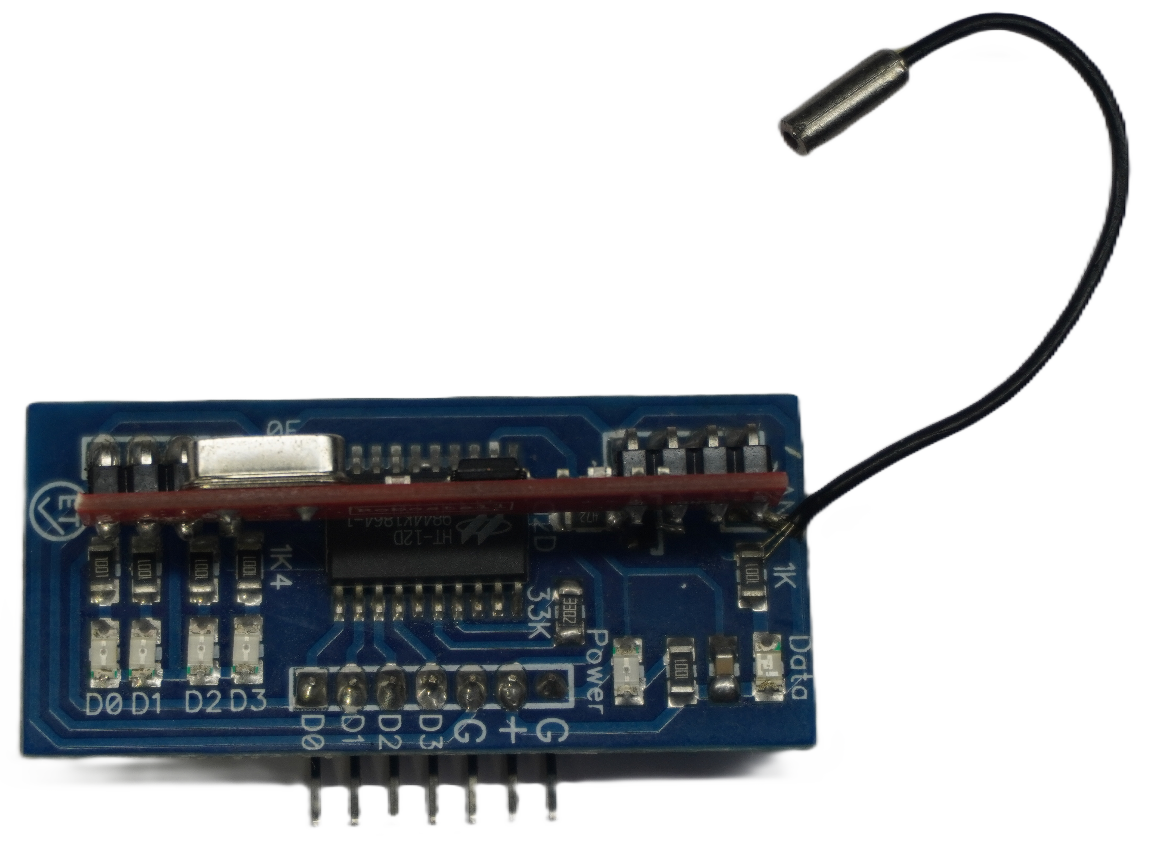
An RF (Radio Frequency) Receiver is an electronic device designed to receive radio signals transmitted at specific frequencies and convert them into electrical signals. These signals can then be processed and used by output devices or for further digital processing. RF receivers are commonly used in remote control systems, wireless communication setups, telemetry, and various other applications where wireless signal reception is required.

Explore Projects Built with RF Receiver

Use Cirkit Designer to design, explore, and prototype these projects online. Some projects support real-time simulation. Click "Open Project" to start designing instantly!
ESP32-Based RF Communication System with 433 MHz Modules
Image of 433 mhz: A project utilizing RF Receiver  in a practical application
This circuit comprises an ESP32 microcontroller connected to a 433 MHz RF transmitter and receiver pair. The ESP32 is programmed to receive and decode RF signals through the receiver module, as well as send RF signals via the transmitter module. Additionally, the ESP32 can communicate with a Bluetooth device to exchange commands and data, and it uses an LED for status indication.
Cirkit Designer LogoOpen Project in Cirkit Designer
433 MHz RF Transmitter and Receiver with Arduino UNO for Wireless Communication
Image of Wireless Communication: A project utilizing RF Receiver  in a practical application
This circuit consists of two Arduino UNO microcontrollers, each connected to an RF 433 MHz Transmitter and a 433 MHz RF Receiver Module. The setup allows for wireless communication between the two Arduinos, enabling them to send and receive data over a 433 MHz RF link.
Cirkit Designer LogoOpen Project in Cirkit Designer
Arduino-Based Doppler Radar with RF Transmission and LCD Display
Image of Doppler Radar: A project utilizing RF Receiver  in a practical application
This circuit features an Arduino UNO microcontroller interfaced with an RF 433 MHz Transmitter, a Transmitter RF Module, an LCD screen with I2C communication, and a doppler radar sensor. The Arduino controls the RF transmission and processes the doppler radar's signal, likely for motion detection purposes. The LCD screen is used to display information or statuses, and the RF modules enable wireless communication, possibly to transmit the processed radar data.
Cirkit Designer LogoOpen Project in Cirkit Designer
Arduino Pro Mini FM Radio with LCD Display and Battery Power
Image of DIY FM Radio RDA5807M V2: A project utilizing RF Receiver  in a practical application
This circuit is a portable FM radio receiver with an integrated display and audio output. It uses an Arduino Pro Mini to control an RDA5807M FM receiver module, an ADS1115 ADC for additional analog inputs, and a PAM8403 amplifier to drive loudspeakers. The circuit also includes a rotary encoder for user input, an LCD screen for displaying information, and a boost converter for power management.
Cirkit Designer LogoOpen Project in Cirkit Designer

Explore Projects Built with RF Receiver

Use Cirkit Designer to design, explore, and prototype these projects online. Some projects support real-time simulation. Click "Open Project" to start designing instantly!
Image of 433 mhz: A project utilizing RF Receiver  in a practical application
ESP32-Based RF Communication System with 433 MHz Modules
This circuit comprises an ESP32 microcontroller connected to a 433 MHz RF transmitter and receiver pair. The ESP32 is programmed to receive and decode RF signals through the receiver module, as well as send RF signals via the transmitter module. Additionally, the ESP32 can communicate with a Bluetooth device to exchange commands and data, and it uses an LED for status indication.
Cirkit Designer LogoOpen Project in Cirkit Designer
Image of Wireless Communication: A project utilizing RF Receiver  in a practical application
433 MHz RF Transmitter and Receiver with Arduino UNO for Wireless Communication
This circuit consists of two Arduino UNO microcontrollers, each connected to an RF 433 MHz Transmitter and a 433 MHz RF Receiver Module. The setup allows for wireless communication between the two Arduinos, enabling them to send and receive data over a 433 MHz RF link.
Cirkit Designer LogoOpen Project in Cirkit Designer
Image of Doppler Radar: A project utilizing RF Receiver  in a practical application
Arduino-Based Doppler Radar with RF Transmission and LCD Display
This circuit features an Arduino UNO microcontroller interfaced with an RF 433 MHz Transmitter, a Transmitter RF Module, an LCD screen with I2C communication, and a doppler radar sensor. The Arduino controls the RF transmission and processes the doppler radar's signal, likely for motion detection purposes. The LCD screen is used to display information or statuses, and the RF modules enable wireless communication, possibly to transmit the processed radar data.
Cirkit Designer LogoOpen Project in Cirkit Designer
Image of DIY FM Radio RDA5807M V2: A project utilizing RF Receiver  in a practical application
Arduino Pro Mini FM Radio with LCD Display and Battery Power
This circuit is a portable FM radio receiver with an integrated display and audio output. It uses an Arduino Pro Mini to control an RDA5807M FM receiver module, an ADS1115 ADC for additional analog inputs, and a PAM8403 amplifier to drive loudspeakers. The circuit also includes a rotary encoder for user input, an LCD screen for displaying information, and a boost converter for power management.
Cirkit Designer LogoOpen Project in Cirkit Designer

Common Applications and Use Cases

  • Remote control systems for TVs, garage doors, and drones
  • Wireless data transmission for telemetry
  • RFID (Radio Frequency Identification) systems
  • Amateur radio equipment
  • Wireless sensor networks

Technical Specifications

Key Technical Details

  • Operating Frequency Range: Typically 300 MHz to 6 GHz (varies by model)
  • Sensitivity: The minimum received signal strength to achieve a specified level of performance
  • Selectivity: Ability to discriminate between the desired signal and unwanted signals
  • IF (Intermediate Frequency): Frequency to which a carrier frequency is shifted as a step in demodulation
  • Supply Voltage: Commonly 3.3V to 5V for most modules
  • Current Consumption: Depends on the operating mode (e.g., active, standby)

Pin Configuration and Descriptions

Pin Number Name Description
1 VCC Power supply input, typically 3.3V to 5V
2 GND Ground connection
3 DATA Data output pin, outputs the demodulated data
4 ANT Antenna connection, for receiving RF signals

Usage Instructions

How to Use the Component in a Circuit

  1. Power Supply: Connect the VCC pin to a power source within the specified voltage range and the GND pin to the ground of the power source.
  2. Antenna: Attach an appropriate antenna to the ANT pin to ensure proper signal reception.
  3. Data Output: Connect the DATA pin to a digital input pin on a microcontroller or other processing unit to read the demodulated data.

Important Considerations and Best Practices

  • Antenna Design: The length and type of the antenna are crucial for optimal reception. Follow the manufacturer's recommendations.
  • Placement: Avoid placing the RF receiver near metal objects or electronic devices that may cause interference.
  • Power Supply: Ensure a clean and stable power supply to prevent noise in the received signal.
  • Data Decoding: Use appropriate decoding algorithms or libraries that match the transmitted signal's modulation and encoding schemes.

Example Code for Arduino UNO

#include <VirtualWire.h>

const int rfReceiverPin = 11; // RF Receiver DATA pin connected to Arduino pin 11

void setup() {
  Serial.begin(9600); // Start the serial communication with the computer
  vw_set_rx_pin(rfReceiverPin); // Set the Virtual Wire library to use the specified pin
  vw_setup(2000); // Bits per sec
  vw_rx_start(); // Start the receiver PLL running
}

void loop() {
  uint8_t buf[VW_MAX_MESSAGE_LEN]; // Buffer to store the received message
  uint8_t buflen = VW_MAX_MESSAGE_LEN; // Maximum message length

  if (vw_get_message(buf, &buflen)) { // Check if a message has been received
    Serial.print("Received: ");
    for (int i = 0; i < buflen; i++) {
      Serial.print(buf[i], HEX); // Print each byte of the message
      Serial.print(' ');
    }
    Serial.println();
  }
}

Troubleshooting and FAQs

Common Issues Users Might Face

  • No Signal Reception: Ensure the antenna is properly connected and the RF receiver is within the transmitter's range.
  • Intermittent Signal: Check for sources of interference and consider relocating the receiver or using a different antenna.
  • Noise in Received Data: Verify the power supply is stable and free of noise. Adding a decoupling capacitor may help.

Solutions and Tips for Troubleshooting

  • Antenna Issues: Experiment with different antenna lengths and types to improve reception.
  • Interference: Use a spectrum analyzer to identify sources of interference and take steps to mitigate them.
  • Signal Strength: Increase the transmitter's power or use a more sensitive receiver to improve signal strength.

FAQs

Q: Can I use any RF receiver with my transmitter? A: The RF receiver must be compatible with the transmitter's frequency and modulation scheme.

Q: How far can the RF receiver receive signals? A: The range depends on the transmitter's power, the receiver's sensitivity, the environment, and the antenna used.

Q: What can I do to extend the range of my RF receiver? A: Use a higher gain antenna, ensure there are no obstructions, and minimize interference from other devices.