
How to Use L293D Motor Driver: Examples, Pinouts, and Specs
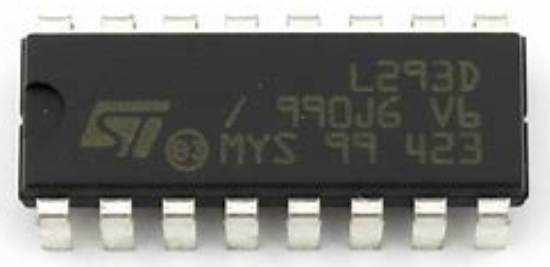
 Design with L293D Motor Driver in Cirkit Designer
Introduction
The L293D is a dual H-bridge motor driver IC designed to control the direction and speed of DC motors and stepper motors. It is capable of driving two motors simultaneously, making it an essential component in robotics, automation, and motor control projects. The IC can handle bidirectional control of motors, allowing for forward and reverse motion, and supports PWM (Pulse Width Modulation) for speed control.
Explore Projects Built with L293D Motor Driver
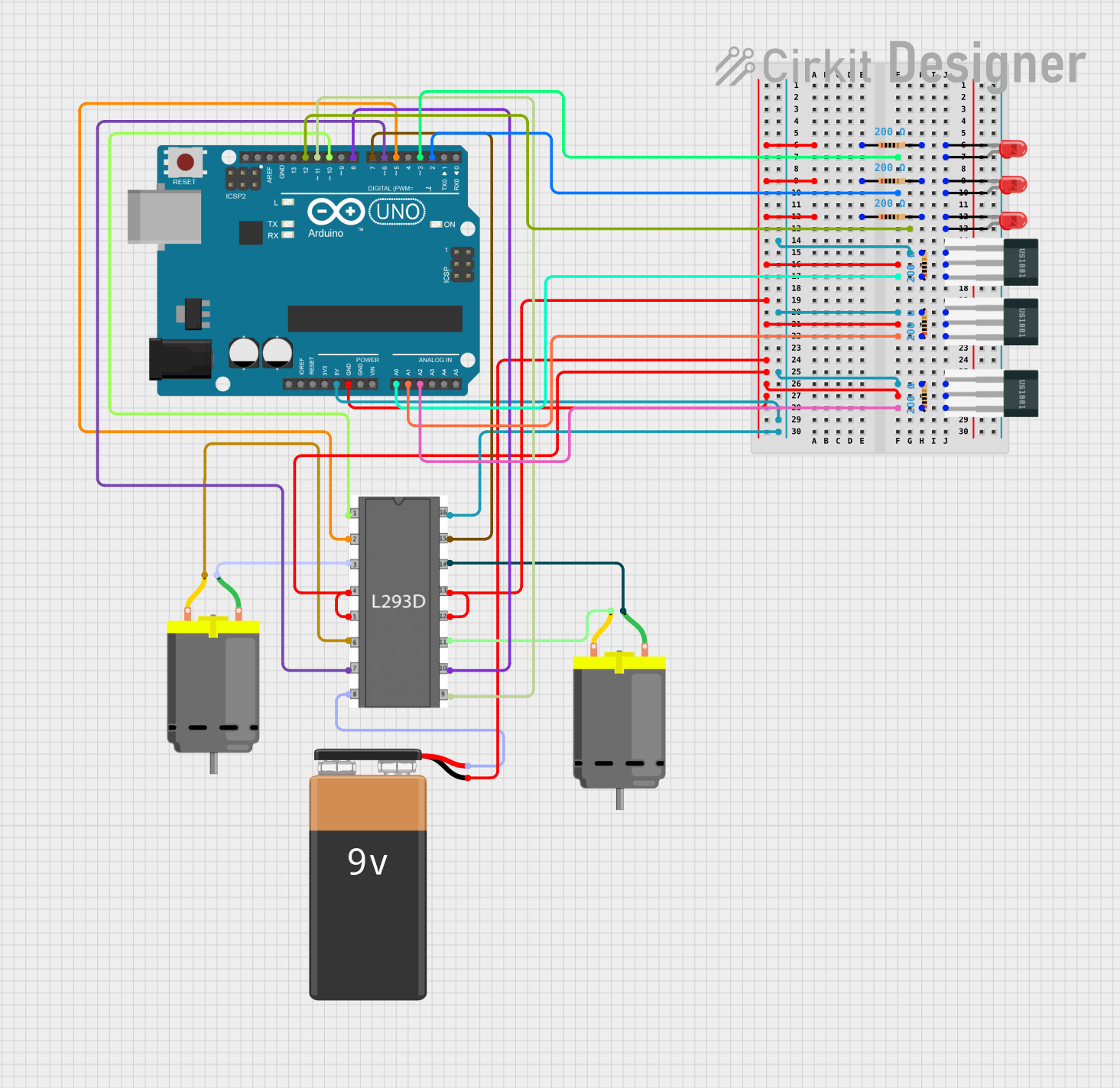 Open Project in Cirkit Designer
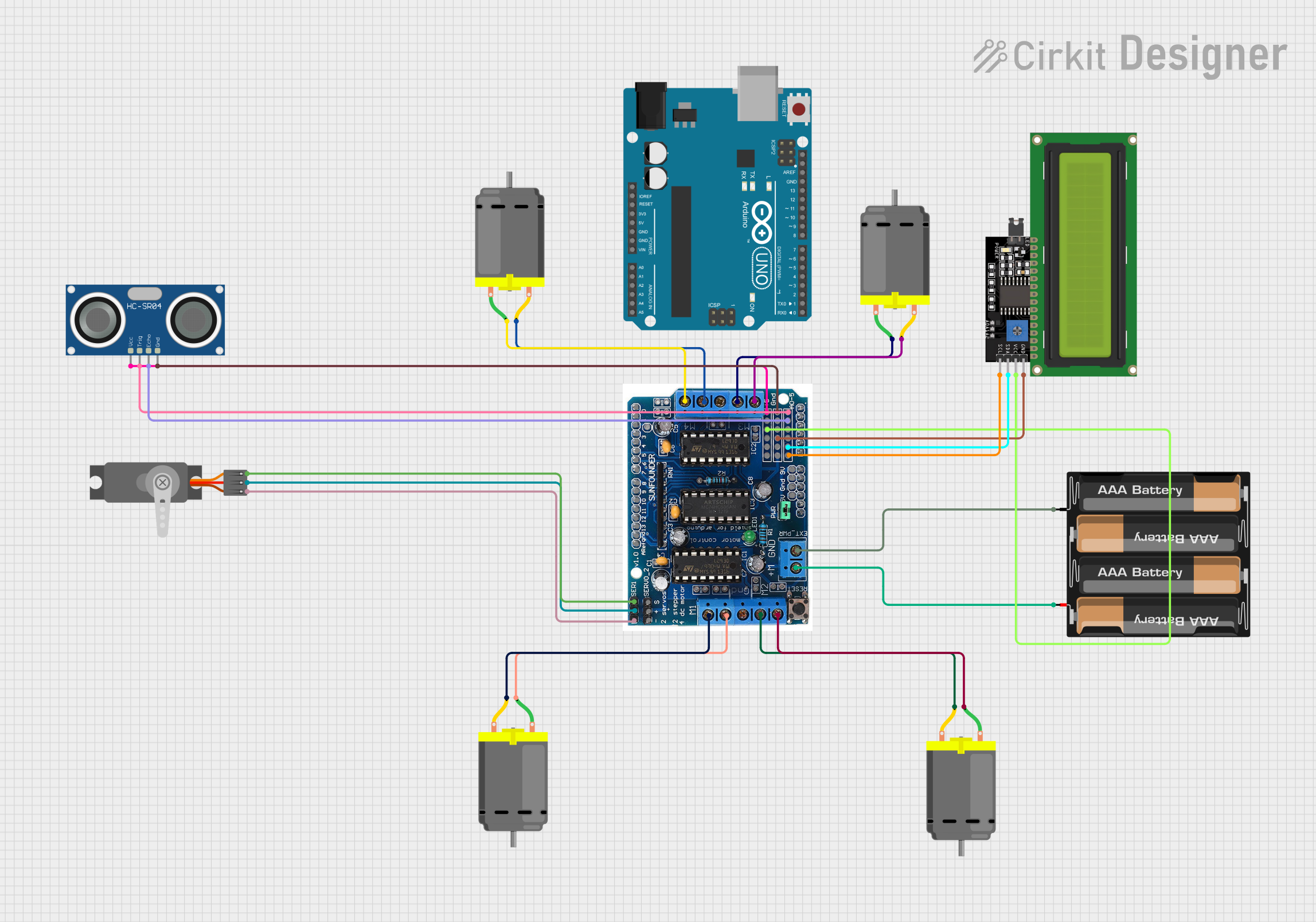 Open Project in Cirkit Designer
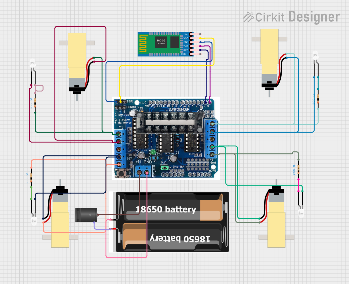 Open Project in Cirkit Designer
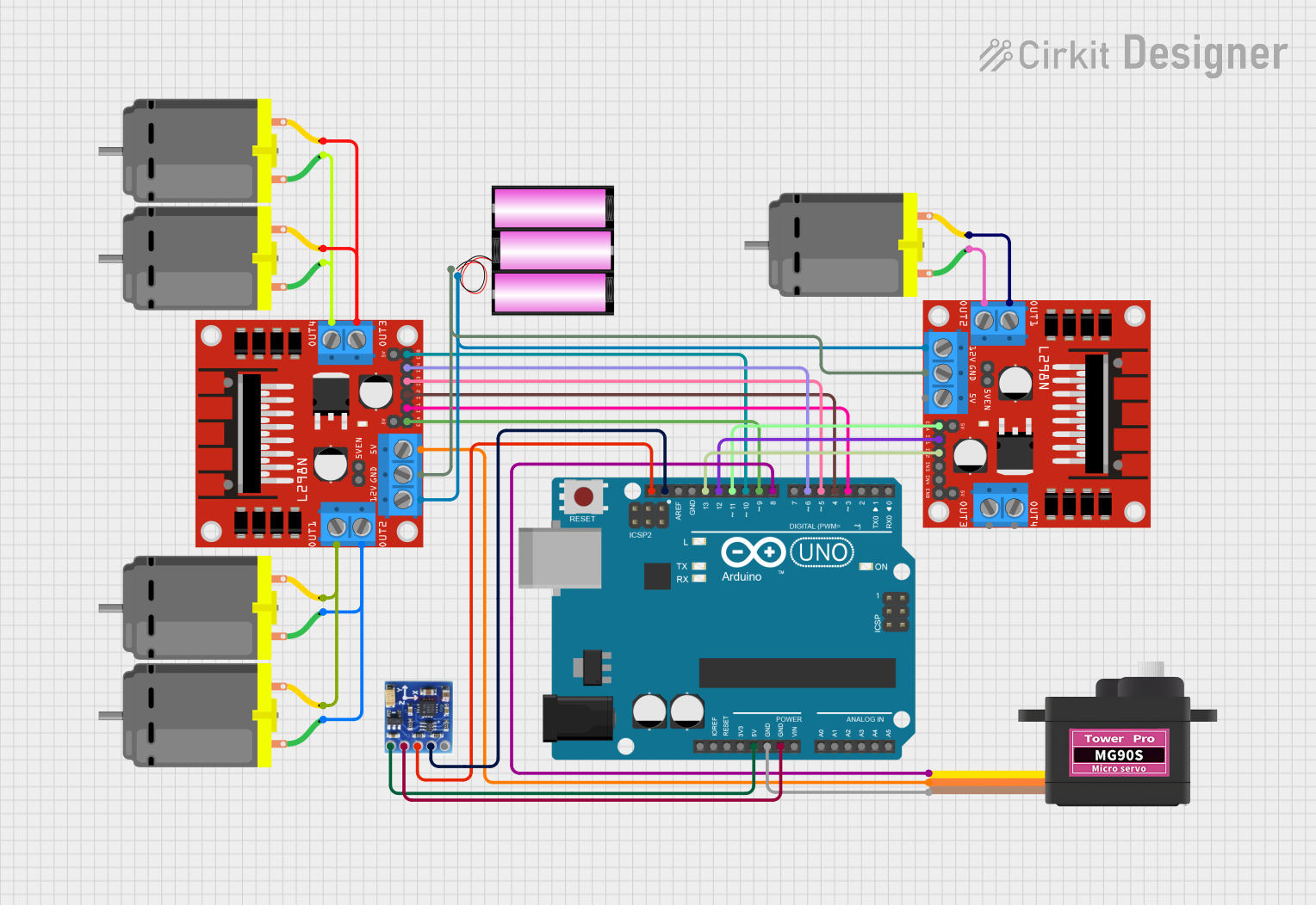 Open Project in Cirkit Designer
Explore Projects Built with L293D Motor Driver
Open Project in Cirkit DesignerOpen Project in Cirkit DesignerOpen Project in Cirkit DesignerOpen Project in Cirkit DesignerCommon Applications
- Robotics (e.g., controlling wheels or robotic arms)
- Automation systems
- Conveyor belts
- Remote-controlled vehicles
- Stepper motor control in CNC machines or 3D printers
Technical Specifications
The L293D is a robust and versatile IC with the following key specifications:
| Parameter | Value |
|---|---|
| Operating Voltage | 4.5V to 36V |
| Output Current (per channel) | 600mA (continuous), 1.2A (peak) |
| Logic Input Voltage | 0V to 7V |
| Enable Input Voltage | High (2.3V to 7V), Low (0V to 1.5V) |
| Power Dissipation | 5W (maximum) |
| Number of Channels | 2 (dual H-bridge) |
| Motor Voltage Range | 4.5V to 36V |
| Operating Temperature | -25°C to +150°C |
Pin Configuration and Descriptions
The L293D comes in a 16-pin DIP (Dual Inline Package). Below is the pinout and description:
| Pin Number | Pin Name | Description |
|---|---|---|
| 1 | Enable 1,2 | Enables H-bridge 1 (High = Enabled, Low = Disabled) |
| 2 | Input 1 | Logic input for H-bridge 1 (controls motor direction) |
| 3 | Output 1 | Output for H-bridge 1 (connect to motor terminal) |
| 4 | GND | Ground (common ground for logic and motor power) |
| 5 | GND | Ground (common ground for logic and motor power) |
| 6 | Output 2 | Output for H-bridge 1 (connect to motor terminal) |
| 7 | Input 2 | Logic input for H-bridge 1 (controls motor direction) |
| 8 | Vcc2 (Motor V+) | Motor supply voltage (4.5V to 36V) |
| 9 | Enable 3,4 | Enables H-bridge 2 (High = Enabled, Low = Disabled) |
| 10 | Input 3 | Logic input for H-bridge 2 (controls motor direction) |
| 11 | Output 3 | Output for H-bridge 2 (connect to motor terminal) |
| 12 | GND | Ground (common ground for logic and motor power) |
| 13 | GND | Ground (common ground for logic and motor power) |
| 14 | Output 4 | Output for H-bridge 2 (connect to motor terminal) |
| 15 | Input 4 | Logic input for H-bridge 2 (controls motor direction) |
| 16 | Vcc1 (Logic V+) | Logic supply voltage (4.5V to 7V) |
Usage Instructions
How to Use the L293D in a Circuit
Power Connections:
- Connect
Vcc1(Pin 16) to the logic voltage (e.g., 5V for Arduino). - Connect
Vcc2(Pin 8) to the motor supply voltage (e.g., 9V or 12V, depending on the motor). - Connect all
GNDpins (Pins 4, 5, 12, 13) to the ground of the power supply.
- Connect
Motor Connections:
- Connect the motor terminals to the output pins (
Output 1andOutput 2for Motor 1,Output 3andOutput 4for Motor 2).
- Connect the motor terminals to the output pins (
Control Logic:
- Use the input pins (
Input 1,Input 2,Input 3,Input 4) to control the direction of the motors. - Enable the H-bridges using the
Enablepins (Enable 1,2for Motor 1,Enable 3,4for Motor 2).
- Use the input pins (
PWM for Speed Control:
- Apply a PWM signal to the
Enablepins to control motor speed.
- Apply a PWM signal to the
Example: Connecting L293D to Arduino UNO
Below is an example of how to control a single DC motor using the L293D and Arduino UNO:
Circuit Connections
- Connect
Vcc1to the Arduino's 5V pin. - Connect
Vcc2to an external 9V power supply. - Connect
GNDto the Arduino's GND pin. - Connect
Input 1to Arduino pin 9. - Connect
Input 2to Arduino pin 10. - Connect
Enable 1,2to Arduino pin 11. - Connect the motor terminals to
Output 1andOutput 2.
Arduino Code
// Define motor control pins
const int enablePin = 11; // Enable pin for Motor 1
const int input1Pin = 9;  // Input 1 for Motor 1
const int input2Pin = 10; // Input 2 for Motor 1

void setup() {
  // Set motor control pins as outputs
  pinMode(enablePin, OUTPUT);
  pinMode(input1Pin, OUTPUT);
  pinMode(input2Pin, OUTPUT);

  // Initialize motor to stop
  digitalWrite(input1Pin, LOW);
  digitalWrite(input2Pin, LOW);
  analogWrite(enablePin, 0); // Set speed to 0
}

void loop() {
  // Rotate motor forward at 50% speed
  digitalWrite(input1Pin, HIGH);
  digitalWrite(input2Pin, LOW);
  analogWrite(enablePin, 128); // PWM value for 50% speed
  delay(2000); // Run for 2 seconds

  // Rotate motor backward at full speed
  digitalWrite(input1Pin, LOW);
  digitalWrite(input2Pin, HIGH);
  analogWrite(enablePin, 255); // PWM value for 100% speed
  delay(2000); // Run for 2 seconds

  // Stop the motor
  digitalWrite(input1Pin, LOW);
  digitalWrite(input2Pin, LOW);
  analogWrite(enablePin, 0); // Set speed to 0
  delay(2000); // Wait for 2 seconds
}
Important Considerations
- Ensure the motor voltage (
Vcc2) matches the motor's rated voltage. - Do not exceed the maximum current rating of 600mA per channel.
- Use a heat sink if the IC becomes too hot during operation.
- Always connect all ground pins to a common ground.
Troubleshooting and FAQs
Common Issues
Motor Not Running:
- Check if the
Enablepin is set to HIGH. - Verify the power supply connections (
Vcc1,Vcc2, and GND). - Ensure the input pins are receiving the correct logic signals.
- Check if the
Motor Running in the Wrong Direction:
- Swap the logic levels on the input pins (e.g., HIGH on
Input 1and LOW onInput 2).
- Swap the logic levels on the input pins (e.g., HIGH on
IC Overheating:
- Ensure the motor's current draw does not exceed 600mA.
- Use a heat sink or reduce the load on the motor.
PWM Not Controlling Speed:
- Verify that the PWM signal is applied to the
Enablepin. - Check the PWM frequency and duty cycle settings in your code.
- Verify that the PWM signal is applied to the
FAQs
Q: Can the L293D drive stepper motors?
A: Yes, the L293D can drive stepper motors by controlling the sequence of inputs to the H-bridges.
Q: Can I use the L293D with a 3.3V microcontroller?
A: Yes, but ensure that the logic voltage (Vcc1) is compatible with the microcontroller's output levels.
Q: What is the difference between L293 and L293D?
A: The L293D includes internal flyback diodes for protection, while the L293 does not.
Q: Can I control more than two motors with one L293D?
A: No, the L293D can control only two motors. For more motors, use additional L293D ICs.