
How to Use RaspIO Duino: Examples, Pinouts, and Specs
 Design with RaspIO Duino in Cirkit Designer
Introduction
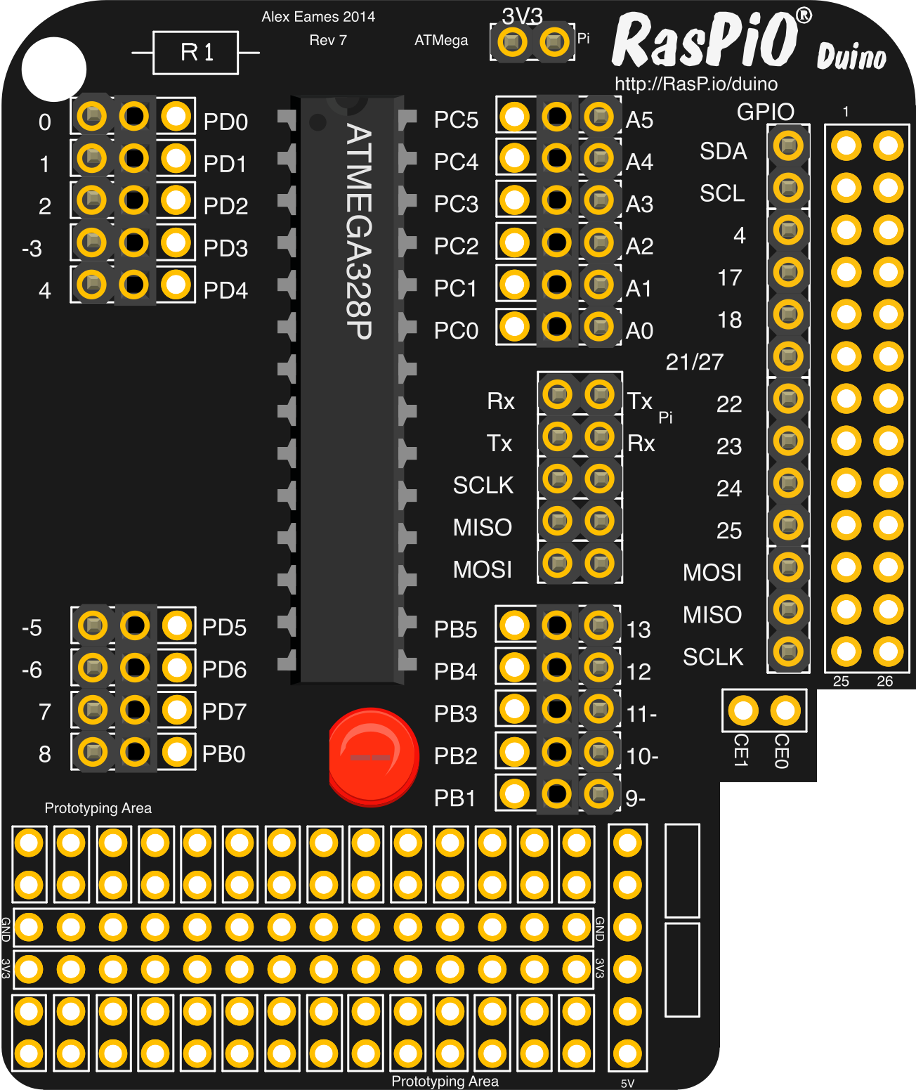
The RaspIO Duino is a versatile microcontroller board that combines the functionality of a Raspberry Pi and an Arduino. It is designed to bridge the gap between the powerful processing capabilities of the Raspberry Pi and the simplicity and flexibility of Arduino. This hybrid board allows users to seamlessly integrate sensors, actuators, and other peripherals into their projects, making it ideal for IoT applications, robotics, home automation, and educational purposes.
Explore Projects Built with RaspIO Duino
 Open Project in Cirkit Designer
 Open Project in Cirkit Designer
 Open Project in Cirkit Designer
 Open Project in Cirkit Designer
Explore Projects Built with RaspIO Duino
Open Project in Cirkit DesignerOpen Project in Cirkit DesignerOpen Project in Cirkit DesignerOpen Project in Cirkit DesignerCommon Applications and Use Cases
- IoT Projects: Collect and process sensor data while leveraging Raspberry Pi's networking capabilities.
- Robotics: Control motors and servos with Arduino's real-time capabilities.
- Home Automation: Build smart home devices with sensor integration and cloud connectivity.
- Education: Teach programming and electronics with a single, versatile platform.
- Prototyping: Quickly develop and test hardware and software solutions.
Technical Specifications
The RaspIO Duino combines the best features of both platforms, offering a wide range of capabilities. Below are the key technical details:
General Specifications
| Feature | Specification |
|---|---|
| Microcontroller | ATmega328P (Arduino-compatible) |
| Processor (Raspberry Pi) | Broadcom BCM2837 (Quad-core ARM Cortex-A53, 1.2 GHz) |
| Operating Voltage | 5V (Arduino) / 5V or 3.3V (Raspberry Pi GPIO) |
| Input Voltage (recommended) | 7-12V (via barrel jack or VIN pin) |
| Digital I/O Pins | 14 (Arduino-compatible, 6 PWM outputs) |
| Analog Input Pins | 6 (Arduino-compatible) |
| GPIO Pins (Raspberry Pi) | 40 (standard Raspberry Pi GPIO header) |
| Communication Interfaces | UART, I2C, SPI, USB |
| Flash Memory | 32 KB (ATmega328P) |
| SRAM | 2 KB (ATmega328P) |
| EEPROM | 1 KB (ATmega328P) |
| Connectivity | Ethernet, Wi-Fi (via Raspberry Pi) |
| Dimensions | 85.6 mm x 56.5 mm |
Pin Configuration and Descriptions
Arduino-Compatible Pins
| Pin | Name | Description |
|---|---|---|
| 0 | RX | UART Receive pin |
| 1 | TX | UART Transmit pin |
| 2-13 | Digital I/O | General-purpose digital input/output pins |
| 3, 5, 6, 9, 10, 11 | PWM | Pulse Width Modulation capable pins |
| A0-A5 | Analog Input | Analog input pins (10-bit resolution) |
| VIN | Voltage Input | External power input (7-12V recommended) |
| GND | Ground | Ground connection |
| 5V | Power Output | Regulated 5V output |
| 3.3V | Power Output | Regulated 3.3V output |
Raspberry Pi GPIO Header
| Pin | Name | Description |
|---|---|---|
| 1 | 3.3V | 3.3V power supply |
| 2 | 5V | 5V power supply |
| 3, 5 | SDA, SCL | I2C communication pins |
| 7, 11, 13, 15 | GPIO Pins | General-purpose input/output pins |
| 8, 10 | TXD, RXD | UART communication pins |
| 9, 14, 20, 25 | GND | Ground pins |
| 19, 21, 23, 24 | SPI Pins | SPI communication pins |
Usage Instructions
How to Use the RaspIO Duino in a Circuit
- Powering the Board:
- Use a 7-12V DC adapter via the barrel jack or VIN pin for Arduino functionality.
- Alternatively, power the Raspberry Pi section via the micro-USB or USB-C port.
- Connecting Sensors and Actuators:
- Use the Arduino-compatible pins for real-time control of sensors and actuators.
- For advanced processing or networking, connect peripherals to the Raspberry Pi GPIO header.
- Programming:
- Program the Arduino section using the Arduino IDE via the USB connection.
- Program the Raspberry Pi section using Python, C++, or other supported languages.
Important Considerations and Best Practices
- Voltage Levels: Ensure that connected peripherals match the voltage levels of the respective pins (5V for Arduino, 3.3V for Raspberry Pi GPIO).
- Power Supply: Avoid powering both sections simultaneously from different sources to prevent ground loops.
- Heat Management: The Raspberry Pi section may generate heat during intensive tasks. Use a heatsink or fan if necessary.
- Communication Between Sections: Use UART, I2C, or SPI to enable communication between the Arduino and Raspberry Pi sections.
Example Code for Arduino Section
Below is an example of how to blink an LED connected to pin 13 of the Arduino section:
// Blink an LED connected to pin 13
void setup() {
  pinMode(13, OUTPUT); // Set pin 13 as an output
}

void loop() {
  digitalWrite(13, HIGH); // Turn the LED on
  delay(1000);            // Wait for 1 second
  digitalWrite(13, LOW);  // Turn the LED off
  delay(1000);            // Wait for 1 second
}
Example Code for Raspberry Pi Section
Below is an example of how to blink an LED connected to GPIO pin 17 using Python:
Import the GPIO library
import RPi.GPIO as GPIO import time
Set up GPIO mode and pin
GPIO.setmode(GPIO.BCM) # Use Broadcom pin numbering GPIO.setup(17, GPIO.OUT) # Set GPIO 17 as an output
try: while True: GPIO.output(17, GPIO.HIGH) # Turn the LED on time.sleep(1) # Wait for 1 second GPIO.output(17, GPIO.LOW) # Turn the LED off time.sleep(1) # Wait for 1 second except KeyboardInterrupt: GPIO.cleanup() # Clean up GPIO settings on exit
Troubleshooting and FAQs
Common Issues and Solutions
The board is not powering on:
- Ensure the power supply is connected to the correct input (barrel jack, VIN, or USB).
- Check that the power supply provides sufficient voltage and current.
Unable to upload code to the Arduino section:
- Verify that the correct COM port is selected in the Arduino IDE.
- Ensure the correct board (Arduino Uno) is selected in the IDE settings.
- Check the USB cable for damage or try a different cable.
Communication between Arduino and Raspberry Pi sections is not working:
- Double-check the wiring for UART, I2C, or SPI connections.
- Ensure that the baud rate or communication settings match on both sides.
Overheating issues:
- Use a heatsink or fan for the Raspberry Pi section during intensive tasks.
- Avoid placing the board in an enclosed space without ventilation.
FAQs
Can I use the Raspberry Pi GPIO pins while the Arduino section is active? Yes, both sections can operate independently, but ensure proper isolation to avoid conflicts.
What programming languages are supported? The Arduino section supports C/C++ via the Arduino IDE, while the Raspberry Pi section supports Python, C++, Java, and more.
Can I power the board using a battery? Yes, you can use a 7-12V battery connected to the VIN pin or barrel jack.
Is the board compatible with Raspberry Pi HATs? Yes, the Raspberry Pi GPIO header is fully compatible with standard HATs.
By following this documentation, you can effectively utilize the RaspIO Duino for a wide range of projects!