How to Use 220V Well Pump Relay: Examples, Pinouts, and Specs
Introduction
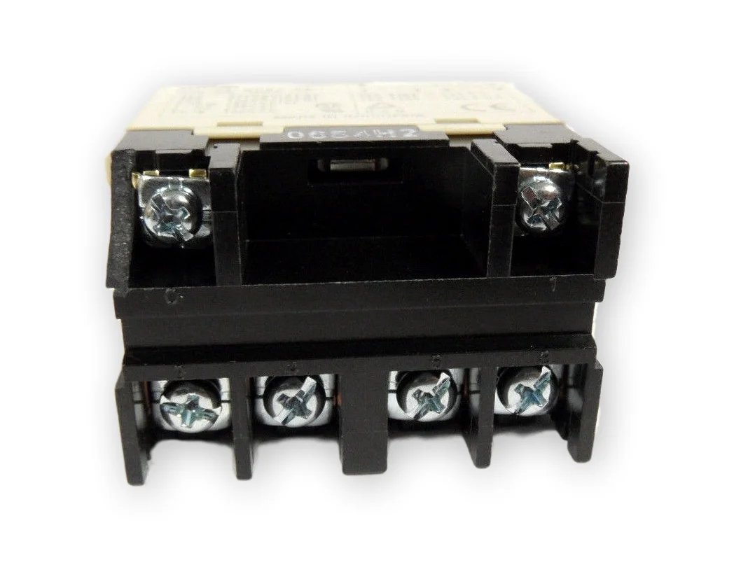
A 220V well pump relay is an electromechanical switch that is used to control the operation of a well pump motor. It operates by receiving input signals that trigger the switching mechanism, allowing high-power well pump motors to be turned on or off. This relay is commonly used in residential and commercial water supply systems to manage the water flow from a well to a storage tank or direct use.
Explore Projects Built with 220V Well Pump Relay
Explore Projects Built with 220V Well Pump Relay
Common Applications and Use Cases
- Residential water wells
- Irrigation systems
- Commercial water supply systems
- Automated water level control
Technical Specifications
Key Technical Details
- Rated Voltage: 220V AC
- Control Voltage: 24V AC/DC
- Maximum Current: 30A
- Contact Configuration: DPST (Double Pole Single Throw)
- Operating Temperature: -40°C to 85°C
Pin Configuration and Descriptions
| Pin Number | Description | Type |
|---|---|---|
| 1 | Coil Input (24V) | Control Input |
| 2 | Coil Ground | Control Input |
| 3 | Line 1 In (220V) | Power Input |
| 4 | Line 1 Out (to Pump) | Power Output |
| 5 | Line 2 In (220V) | Power Input |
| 6 | Line 2 Out (to Pump) | Power Output |
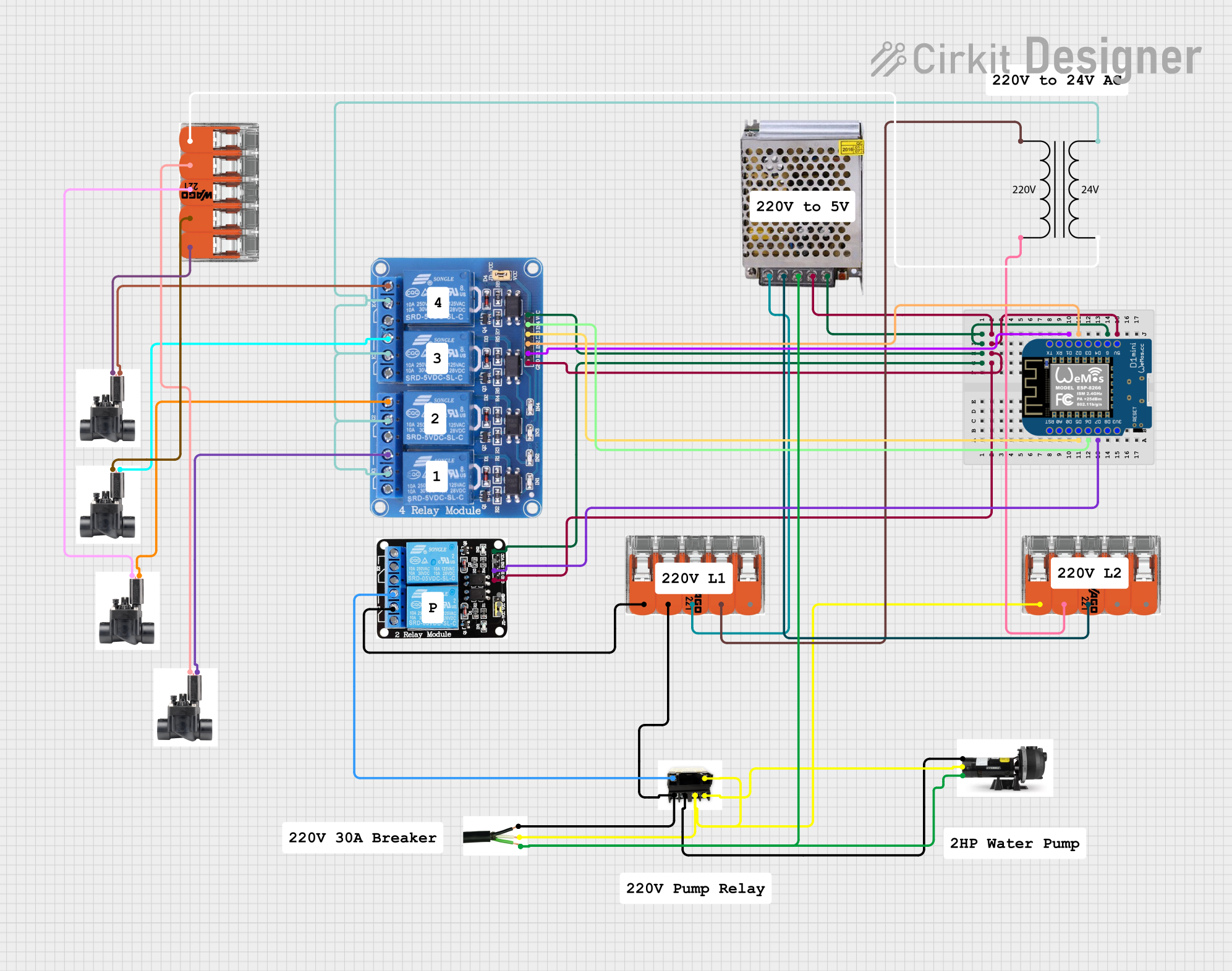
Usage Instructions
How to Use the Component in a Circuit
- Power Supply Connection: Connect the 24V control voltage to pins 1 and 2 for the relay coil.
- Load Connection: Connect the 220V AC supply line to pins 3 and 5. Connect the well pump motor lines to pins 4 and 6.
- Signal Input: Apply the control voltage to the coil to switch the relay on, allowing current to flow to the well pump motor.
Important Considerations and Best Practices
- Ensure that the power supply and load connections are secure and comply with local electrical codes.
- Use a fuse or circuit breaker rated for the pump's current to protect against overcurrent conditions.
- Always disconnect the power before servicing the relay or the pump.
- Test the relay operation in a safe environment before deploying it in a live system.
Troubleshooting and FAQs
Common Issues Users Might Face
- Relay Does Not Activate: Check the control voltage and connections to the coil. Ensure that the control signal is present.
- Pump Does Not Start: Verify that the 220V supply is connected and that the relay contacts are closing properly. Check for continuity across pins 3 to 4 and 5 to 6 when the relay is activated.
- Intermittent Operation: Inspect for loose connections or damaged wires. Ensure that the relay is not being overloaded beyond its rated current.
Solutions and Tips for Troubleshooting
- If the relay does not activate, ensure that the control voltage is within the specified range and that the wiring is correct.
- For a pump that does not start, check the pump motor and its connections for any faults.
- In case of intermittent operation, consider replacing the relay if it shows signs of damage or wear.
FAQs
Q: Can this relay be used with a 24V control system?
- A: Yes, the relay is designed to be operated with a 24V control signal.
Q: What should I do if the relay gets hot during operation?
- A: Check if the current through the relay exceeds the rated value. If so, reduce the load or use a relay with a higher current rating.
Q: How can I test the relay functionality?
- A: Apply the control voltage to the coil and use a multimeter to check for continuity across the output contacts when activated.
If this relay is to be used with an Arduino UNO for control purposes, the following example code can be used to activate the relay:
// Define the relay control pin
const int relayPin = 7;

void setup() {
  // Set the relay control pin as an output
  pinMode(relayPin, OUTPUT);
}

void loop() {
  // Turn on the relay (activate the well pump)
  digitalWrite(relayPin, HIGH);
  delay(5000); // Keep the relay on for 5 seconds

  // Turn off the relay (deactivate the well pump)
  digitalWrite(relayPin, LOW);
  delay(5000); // Keep the relay off for 5 seconds
}
Note: The Arduino operates at 5V and cannot directly switch a 220V AC load. A separate 24V control signal is required to activate the relay coil. The above code assumes the use of an additional relay module or transistor circuit to interface the Arduino with the 24V control signal for the well pump relay. Always ensure proper isolation when dealing with high voltage circuits.