Cirkit Designer Logo
Cirkit Designer
Your all-in-one circuit design IDE
Home / 
Component Documentation

How to Use RC 27mhz Transmitter: Examples, Pinouts, and Specs

Image of RC 27mhz Transmitter
Cirkit Designer LogoDesign with RC 27mhz Transmitter in Cirkit Designer

Introduction

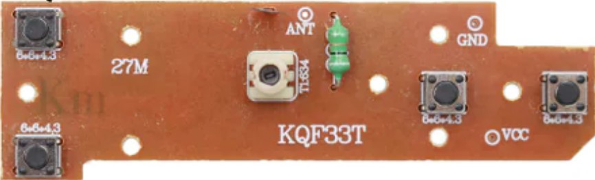
The RC 27MHz Transmitter is a remote control device operating at a frequency of 27 MHz. It is commonly used for controlling remote-controlled (RC) cars, boats, and other RC devices. This transmitter is a crucial component in the RC hobbyist community, providing reliable and straightforward control over various RC models.

Explore Projects Built with RC 27mhz Transmitter

Use Cirkit Designer to design, explore, and prototype these projects online. Some projects support real-time simulation. Click "Open Project" to start designing instantly!
433 MHz RF Transmitter and Receiver with Arduino UNO for Wireless Communication
Image of Wireless Communication: A project utilizing RC 27mhz Transmitter in a practical application
This circuit consists of two Arduino UNO microcontrollers, each connected to an RF 433 MHz Transmitter and a 433 MHz RF Receiver Module. The setup allows for wireless communication between the two Arduinos, enabling them to send and receive data over a 433 MHz RF link.
Cirkit Designer LogoOpen Project in Cirkit Designer
Arduino-Based Doppler Radar with RF Transmission and LCD Display
Image of Doppler Radar: A project utilizing RC 27mhz Transmitter in a practical application
This circuit features an Arduino UNO microcontroller interfaced with an RF 433 MHz Transmitter, a Transmitter RF Module, an LCD screen with I2C communication, and a doppler radar sensor. The Arduino controls the RF transmission and processes the doppler radar's signal, likely for motion detection purposes. The LCD screen is used to display information or statuses, and the RF modules enable wireless communication, possibly to transmit the processed radar data.
Cirkit Designer LogoOpen Project in Cirkit Designer
Arduino UNO with 433MHz RF Module for Wireless Communication
Image of Receiver: A project utilizing RC 27mhz Transmitter in a practical application
This circuit consists of an Arduino UNO connected to an RXN433MHz radio frequency module. The Arduino provides 5V power and ground to the RF module and is configured to communicate with it via digital pin D11. Additionally, a multimeter is connected with alligator clip cables to measure the voltage supplied to the RF module.
Cirkit Designer LogoOpen Project in Cirkit Designer
ESP32-Based RF Communication System with 433 MHz Modules
Image of 433 mhz: A project utilizing RC 27mhz Transmitter in a practical application
This circuit comprises an ESP32 microcontroller connected to a 433 MHz RF transmitter and receiver pair. The ESP32 is programmed to receive and decode RF signals through the receiver module, as well as send RF signals via the transmitter module. Additionally, the ESP32 can communicate with a Bluetooth device to exchange commands and data, and it uses an LED for status indication.
Cirkit Designer LogoOpen Project in Cirkit Designer

Explore Projects Built with RC 27mhz Transmitter

Use Cirkit Designer to design, explore, and prototype these projects online. Some projects support real-time simulation. Click "Open Project" to start designing instantly!
Image of Wireless Communication: A project utilizing RC 27mhz Transmitter in a practical application
433 MHz RF Transmitter and Receiver with Arduino UNO for Wireless Communication
This circuit consists of two Arduino UNO microcontrollers, each connected to an RF 433 MHz Transmitter and a 433 MHz RF Receiver Module. The setup allows for wireless communication between the two Arduinos, enabling them to send and receive data over a 433 MHz RF link.
Cirkit Designer LogoOpen Project in Cirkit Designer
Image of Doppler Radar: A project utilizing RC 27mhz Transmitter in a practical application
Arduino-Based Doppler Radar with RF Transmission and LCD Display
This circuit features an Arduino UNO microcontroller interfaced with an RF 433 MHz Transmitter, a Transmitter RF Module, an LCD screen with I2C communication, and a doppler radar sensor. The Arduino controls the RF transmission and processes the doppler radar's signal, likely for motion detection purposes. The LCD screen is used to display information or statuses, and the RF modules enable wireless communication, possibly to transmit the processed radar data.
Cirkit Designer LogoOpen Project in Cirkit Designer
Image of Receiver: A project utilizing RC 27mhz Transmitter in a practical application
Arduino UNO with 433MHz RF Module for Wireless Communication
This circuit consists of an Arduino UNO connected to an RXN433MHz radio frequency module. The Arduino provides 5V power and ground to the RF module and is configured to communicate with it via digital pin D11. Additionally, a multimeter is connected with alligator clip cables to measure the voltage supplied to the RF module.
Cirkit Designer LogoOpen Project in Cirkit Designer
Image of 433 mhz: A project utilizing RC 27mhz Transmitter in a practical application
ESP32-Based RF Communication System with 433 MHz Modules
This circuit comprises an ESP32 microcontroller connected to a 433 MHz RF transmitter and receiver pair. The ESP32 is programmed to receive and decode RF signals through the receiver module, as well as send RF signals via the transmitter module. Additionally, the ESP32 can communicate with a Bluetooth device to exchange commands and data, and it uses an LED for status indication.
Cirkit Designer LogoOpen Project in Cirkit Designer

Technical Specifications

Key Technical Details

Parameter Value
Operating Frequency 27 MHz
Voltage 9V (typically from a 9V battery)
Current Consumption 10-20 mA
Modulation Type AM (Amplitude Modulation)
Range Up to 100 meters
Channels 2-4 channels

Pin Configuration and Descriptions

Pin Number Pin Name Description
1 VCC Power supply (9V)
2 GND Ground
3 CH1 Channel 1 signal output
4 CH2 Channel 2 signal output
5 CH3 Channel 3 signal output (if available)
6 CH4 Channel 4 signal output (if available)

Usage Instructions

How to Use the Component in a Circuit

  1. Power Supply: Connect the VCC pin to a 9V power source and the GND pin to the ground.
  2. Signal Output: Connect the CH1, CH2, CH3, and CH4 pins to the corresponding inputs of the RC receiver.
  3. Antenna: Ensure the transmitter has a properly connected antenna to maximize the range and reliability of the signal.

Important Considerations and Best Practices

  • Power Source: Always use a fresh 9V battery to ensure consistent performance.
  • Antenna Position: Keep the antenna fully extended and away from metal objects to avoid signal interference.
  • Range Testing: Test the range in an open area to ensure the transmitter covers the required distance.
  • Channel Matching: Ensure the transmitter and receiver are set to the same channel to avoid control issues.

Troubleshooting and FAQs

Common Issues Users Might Face

  1. No Signal Transmission

    • Solution: Check the battery and ensure it is properly connected and charged. Verify that the antenna is properly connected and not damaged.
  2. Short Range

    • Solution: Ensure the antenna is fully extended and positioned correctly. Check for any sources of interference nearby, such as other electronic devices operating at similar frequencies.
  3. Interference with Other Devices

    • Solution: Change the channel on both the transmitter and receiver to a less crowded frequency. Ensure that no other RC devices are operating on the same frequency nearby.

FAQs

  1. Q: Can I use a different power source other than a 9V battery?

    • A: It is recommended to use a 9V battery as specified. Using a different power source may affect the performance and reliability of the transmitter.
  2. Q: How can I increase the range of my transmitter?

    • A: Ensure the antenna is fully extended and positioned correctly. Avoid obstructions and interference from other electronic devices. Using a high-quality antenna can also help improve range.
  3. Q: What should I do if my transmitter is not working at all?

    • A: Check the battery and connections. Ensure the transmitter and receiver are on the same channel. If the problem persists, consult the manufacturer or seek professional assistance.

Example Code for Arduino UNO

If you are using the RC 27MHz Transmitter with an Arduino UNO, you can use the following example code to read the signals from the transmitter:

// Example code to read signals from RC 27MHz Transmitter using Arduino UNO

const int ch1Pin = 2; // Channel 1 input pin
const int ch2Pin = 3; // Channel 2 input pin

void setup() {
  Serial.begin(9600); // Initialize serial communication
  pinMode(ch1Pin, INPUT); // Set channel 1 pin as input
  pinMode(ch2Pin, INPUT); // Set channel 2 pin as input
}

void loop() {
  int ch1Value = pulseIn(ch1Pin, HIGH); // Read pulse width from channel 1
  int ch2Value = pulseIn(ch2Pin, HIGH); // Read pulse width from channel 2

  Serial.print("Channel 1: ");
  Serial.print(ch1Value);
  Serial.print(" us, Channel 2: ");
  Serial.print(ch2Value);
  Serial.println(" us");

  delay(100); // Delay for readability
}

This code reads the pulse width from the transmitter's channels and prints the values to the serial monitor. Ensure the transmitter is powered and the signal pins are connected to the appropriate Arduino pins.

By following this documentation, users can effectively utilize the RC 27MHz Transmitter in their RC projects, ensuring reliable and efficient control over their remote-controlled devices.