
How to Use ATTINY13: Examples, Pinouts, and Specs
 Design with ATTINY13 in Cirkit Designer
Introduction
The ATtiny13 is a small, low-power 8-bit microcontroller developed by Microchip Technology as part of the AVR family. It is designed for simple embedded applications where size, power efficiency, and cost are critical. With 1 KB of flash memory, 64 bytes of SRAM, and 8 GPIO pins, the ATtiny13 is ideal for compact designs requiring basic processing capabilities.
Explore Projects Built with ATTINY13
 Open Project in Cirkit Designer
 Open Project in Cirkit Designer
 Open Project in Cirkit Designer
 Open Project in Cirkit Designer
Explore Projects Built with ATTINY13
Open Project in Cirkit DesignerOpen Project in Cirkit DesignerOpen Project in Cirkit DesignerOpen Project in Cirkit DesignerCommon Applications
- LED control and lighting systems
- Small sensor-based projects
- Battery-powered devices
- Simple motor control
- IoT devices with minimal processing requirements
Technical Specifications
The ATtiny13 is a versatile microcontroller with the following key specifications:
| Parameter | Value |
|---|---|
| Architecture | 8-bit AVR RISC |
| Operating Voltage | 2.7V to 5.5V |
| Flash Memory | 1 KB |
| SRAM | 64 bytes |
| EEPROM | 64 bytes |
| Clock Speed | Up to 20 MHz (with external clock) |
| GPIO Pins | 8 |
| ADC Resolution | 10-bit |
| Power Consumption (Active) | ~240 µA at 1 MHz, 1.8V |
| Package Types | 8-pin PDIP, SOIC, or MLF |
Pin Configuration and Descriptions
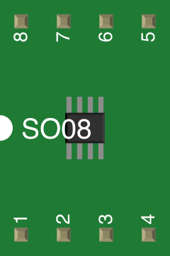
The ATtiny13 is available in an 8-pin package. Below is the pinout and description:
| Pin Number | Pin Name | Description |
|---|---|---|
| 1 | PB5 (RESET) | Reset pin (active low) / GPIO |
| 2 | PB3 (ADC3) | GPIO / Analog input channel 3 |
| 3 | PB4 (ADC2) | GPIO / Analog input channel 2 |
| 4 | GND | Ground |
| 5 | PB0 (ADC0) | GPIO / Analog input channel 0 |
| 6 | PB1 (ADC1) | GPIO / Analog input channel 1 |
| 7 | PB2 (ADC2) | GPIO / Analog input channel 2 / External clock |
| 8 | VCC | Power supply (2.7V to 5.5V) |
Usage Instructions
The ATtiny13 is straightforward to use in embedded systems. Below are the steps and considerations for integrating it into your project.
Basic Circuit Setup
- Power Supply: Connect the VCC pin to a 2.7V–5.5V power source and the GND pin to ground.
- Reset Pin: If not used, connect the RESET pin (PB5) to VCC through a 10kΩ pull-up resistor.
- Clock Source: The ATtiny13 has an internal 9.6 MHz RC oscillator. For higher precision, an external clock can be connected to PB2.
- GPIO Configuration: Configure the GPIO pins (PB0–PB4) as input or output in your code.
Programming the ATtiny13
The ATtiny13 can be programmed using an ISP (In-System Programmer) such as the USBasp or Arduino as ISP. Below is an example of programming the ATtiny13 using an Arduino UNO.
Arduino UNO as ISP
Connect the ATtiny13 to the Arduino UNO as follows:
- ATtiny13 Pin 1 (RESET) → Arduino Pin 10
- ATtiny13 Pin 4 (GND) → Arduino GND
- ATtiny13 Pin 8 (VCC) → Arduino 5V
- ATtiny13 Pin 7 (SCK) → Arduino Pin 13
- ATtiny13 Pin 6 (MISO) → Arduino Pin 12
- ATtiny13 Pin 5 (MOSI) → Arduino Pin 11
Upload the "ArduinoISP" sketch to the Arduino UNO from the Arduino IDE.
Use the following example code to blink an LED connected to PB0 (Pin 5 on the ATtiny13):
// Blink an LED on PB0 (Pin 5 of ATtiny13)

#define LED_PIN 0 // PB0 is pin 0 in ATtiny13's pin mapping

void setup() {
  pinMode(LED_PIN, OUTPUT); // Set PB0 as an output pin
}

void loop() {
  digitalWrite(LED_PIN, HIGH); // Turn the LED on
  delay(500);                  // Wait for 500 milliseconds
  digitalWrite(LED_PIN, LOW);  // Turn the LED off
  delay(500);                  // Wait for 500 milliseconds
}
- Use the Arduino IDE to burn the bootloader and upload the code to the ATtiny13.
Best Practices
- Use decoupling capacitors (e.g., 0.1 µF) between VCC and GND to stabilize the power supply.
- Avoid exceeding the maximum voltage and current ratings to prevent damage.
- Use pull-up or pull-down resistors for unused pins to avoid floating states.
Troubleshooting and FAQs
Common Issues
The ATtiny13 is not responding to programming commands.
- Ensure all connections between the programmer and the ATtiny13 are secure.
- Verify that the correct board and programmer settings are selected in the Arduino IDE.
The LED does not blink as expected.
- Double-check the LED polarity and resistor value.
- Ensure the correct pin number is used in the code.
The microcontroller overheats.
- Check for short circuits or excessive current draw on the GPIO pins.
- Verify that the supply voltage is within the specified range (2.7V–5.5V).
FAQs
Q: Can the ATtiny13 run on batteries?
A: Yes, the ATtiny13 is designed for low-power applications and can run on batteries. Use a voltage regulator if the battery voltage exceeds 5.5V.
Q: How do I use the ADC feature?
A: The ATtiny13 has a 10-bit ADC. Configure the ADC registers in your code to read analog signals from PB0–PB3.
Q: Can I use the ATtiny13 with an external crystal oscillator?
A: No, the ATtiny13 does not support external crystal oscillators. However, it can use an external clock signal on PB2.
By following this documentation, you can effectively integrate the ATtiny13 into your projects and troubleshoot common issues.