How to Use LM2621: Examples, Pinouts, and Specs
Introduction
The LM2621 is a high-efficiency, step-up DC-DC voltage converter designed for battery-powered and low-input voltage systems. It is capable of converting voltages as low as 1.14V to a higher output voltage, which is adjustable from 1.24V to 14V. The LM2621 is particularly useful in applications where the input voltage is below the desired output voltage, such as portable devices, handheld electronics, and power backup systems.
Explore Projects Built with LM2621


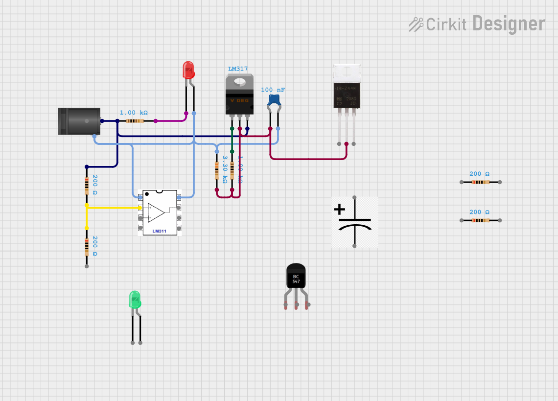

Explore Projects Built with LM2621
Common Applications
- Battery-powered devices
- Portable electronics
- Power backup systems
- Low-power wireless modules
Technical Specifications
Key Technical Details
- Input Voltage Range: 1.14V to 14V
- Output Voltage Range: 1.24V to 14V (adjustable)
- Switching Frequency: Up to 2 MHz
- Quiescent Current: 85 µA typical
- Maximum Output Current: Depends on input voltage and inductor choice
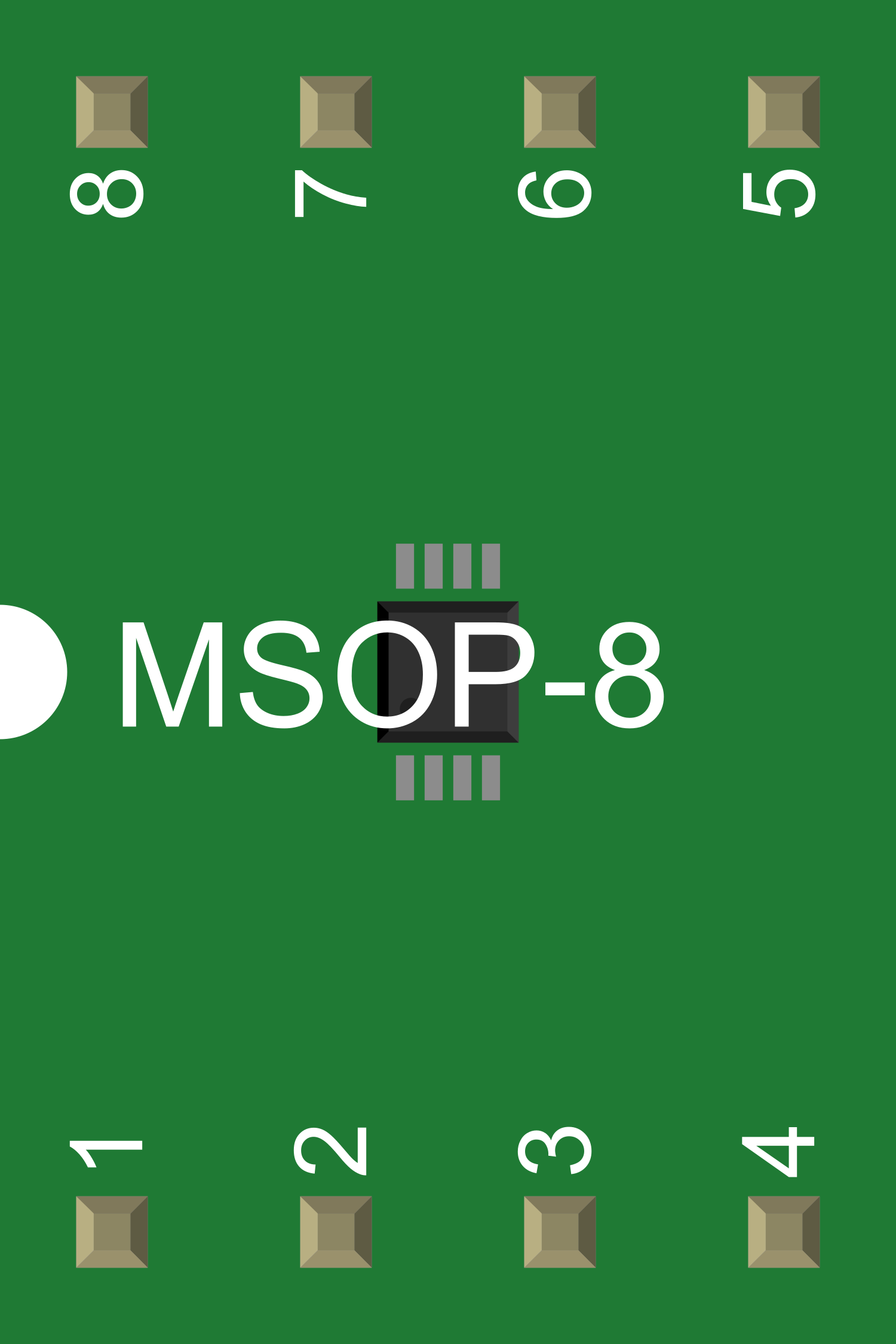
Pin Configuration and Descriptions
| Pin Number | Name | Description |
|---|---|---|
| 1 | SW | Switch node, connects to the inductor and diode |
| 2 | VIN | Input voltage supply pin |
| 3 | GND | Ground reference |
| 4 | FB | Feedback pin, sets the output voltage with a voltage divider |
| 5 | ON/OFF | Chip enable pin, active high |
| 6 | SD | Shutdown pin, active low |
Usage Instructions
How to Use the LM2621 in a Circuit
- Power Supply Connection: Connect the input voltage to the VIN pin and ground to the GND pin.
- Output Voltage Setting: Connect a voltage divider from the output to the FB pin to set the desired output voltage.
- Inductor Selection: Choose an appropriate inductor value based on the desired output current and switching frequency.
- Diode Selection: Select a Schottky diode with a low forward voltage drop and a current rating exceeding the maximum output current.
- Capacitor Selection: Use input and output capacitors to minimize voltage ripple. The values depend on the output current and voltage.
- Enable/Disable: Control the ON/OFF pin to enable or disable the device. Pulling the SD pin low will put the device into shutdown mode.
Important Considerations and Best Practices
- Ensure that the input voltage does not exceed the maximum rating.
- The output voltage should be set accurately using precision resistors for the feedback voltage divider.
- Keep the switching paths as short as possible to reduce EMI and improve efficiency.
- Place input and output capacitors close to the device pins to minimize noise and voltage spikes.
- Use a proper heat-sinking method if the device is expected to handle high power levels.
Troubleshooting and FAQs
Common Issues
- Insufficient Output Voltage: Check the feedback voltage divider and ensure that the resistors are of the correct value and tolerance.
- Excessive Noise or Ripple: Verify the input and output capacitor values and ESR ratings. Ensure that the layout minimizes the loop area of the switching paths.
- Overheating: Ensure that the inductor and diode are rated for the current and that the thermal management is adequate.
Solutions and Tips for Troubleshooting
- If the output voltage is not as expected, recheck the feedback network and ensure that the ON/OFF pin is not inadvertently pulled low.
- For noise issues, consider increasing the capacitance or improving the PCB layout.
- If the device overheats, check the power dissipation and consider improving airflow or adding a heatsink.
FAQs
Q: Can the LM2621 be used with an input voltage higher than the output voltage? A: No, the LM2621 is a boost converter and is designed to step up a lower input voltage to a higher output voltage.
Q: What is the maximum output current the LM2621 can provide? A: The maximum output current depends on the input voltage, inductor size, and thermal conditions. Refer to the datasheet for detailed calculations.
Q: How do I enable the LM2621? A: Apply a high logic level to the ON/OFF pin to enable the LM2621. Pulling the SD pin low will shut down the device.
Example Code for Arduino UNO
// Example code to control the LM2621 with an Arduino UNO
const int enablePin = 9; // Connect to the ON/OFF pin of LM2621

void setup() {
  pinMode(enablePin, OUTPUT);
  // Start with the LM2621 disabled
  digitalWrite(enablePin, LOW);
}

void loop() {
  // Enable the LM2621
  digitalWrite(enablePin, HIGH);
  delay(5000); // Keep the LM2621 enabled for 5 seconds

  // Disable the LM2621
  digitalWrite(enablePin, LOW);
  delay(5000); // Keep the LM2621 disabled for 5 seconds
}
This example demonstrates how to enable and disable the LM2621 using an Arduino UNO. The enablePin is connected to the ON/OFF pin of the LM2621, and the code toggles this pin to control the power state of the LM2621.