How to Use BMS: Examples, Pinouts, and Specs
Introduction
A Battery Management System (BMS) is an electronic system designed to manage rechargeable batteries. It monitors the battery's state, calculates secondary data (such as charge and health), reports this data, and controls the battery's operating environment. The BMS ensures safe operation, optimizes performance, and extends the battery's lifespan.
Explore Projects Built with BMS


Explore Projects Built with BMS
Common Applications and Use Cases
- Electric vehicles (EVs) and hybrid electric vehicles (HEVs)
- Renewable energy storage systems (e.g., solar and wind power)
- Consumer electronics (e.g., laptops, smartphones, and power banks)
- Uninterruptible Power Supplies (UPS)
- Industrial and medical equipment requiring reliable battery operation
Technical Specifications
Key Technical Details
| Parameter | Value/Range |
|---|---|
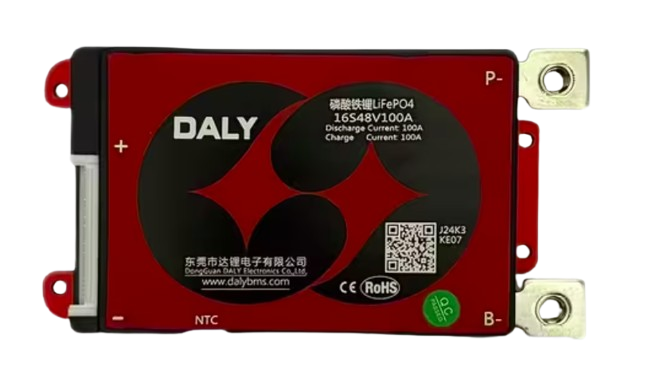
| Input Voltage Range | 3.7V to 60V (varies by model) |
| Supported Battery Types | Lithium-ion, LiFePO4, NiMH, etc. |
| Maximum Charge Current | 1A to 100A (model-dependent) |
| Overcharge Protection | Configurable (e.g., 4.2V per cell) |
| Over-discharge Protection | Configurable (e.g., 2.5V per cell) |
| Balancing Current | 50mA to 200mA |
| Communication Protocols | I2C, UART, CAN (varies by model) |
| Operating Temperature | -20°C to 60°C |
| Dimensions | Varies by model |
Pin Configuration and Descriptions
| Pin Name | Description |
|---|---|
| B+ | Battery positive terminal |
| B- | Battery negative terminal |
| P+ | Load/charger positive terminal |
| P- | Load/charger negative terminal |
| C+ | Charger positive terminal (if separate from P+) |
| C- | Charger negative terminal (if separate from P-) |
| Balance Pins | Connect to individual battery cells for voltage balancing |
| Communication | I2C, UART, or CAN pins for data exchange with microcontrollers or systems |
Usage Instructions
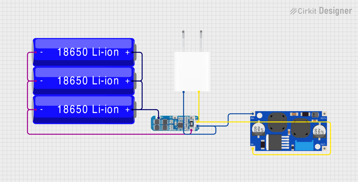
How to Use the BMS in a Circuit
Connect the Battery Pack:
- Connect the battery pack's positive terminal to the B+ pin and the negative terminal to the B- pin.
- For multi-cell configurations, connect the balance wires to the corresponding balance pins.
Connect the Load and Charger:
- Attach the load's positive and negative terminals to P+ and P-, respectively.
- If the charger has separate terminals, connect them to C+ and C-.
Configure the BMS:
- Use the communication interface (e.g., I2C or UART) to configure parameters such as overcharge/over-discharge thresholds and balancing settings.
Monitor the System:
- Use a microcontroller or monitoring software to read battery data (e.g., voltage, current, temperature) via the communication interface.
Important Considerations and Best Practices
- Battery Compatibility: Ensure the BMS is compatible with the battery chemistry and configuration (e.g., number of cells).
- Heat Management: Avoid overheating by ensuring proper ventilation or adding heat sinks if necessary.
- Wiring: Use appropriate wire gauges to handle the current without excessive resistance or heating.
- Balancing: Regularly check and enable cell balancing to maintain uniform cell voltages.
- Firmware Updates: If applicable, keep the BMS firmware updated for improved performance and safety.
Example: Connecting a BMS to an Arduino UNO
Below is an example of using an Arduino UNO to monitor a BMS via I2C communication.
#include <Wire.h> // Include the Wire library for I2C communication

#define BMS_I2C_ADDRESS 0x10 // Replace with your BMS's I2C address

void setup() {
  Wire.begin(); // Initialize I2C communication
  Serial.begin(9600); // Start serial communication for debugging
  Serial.println("BMS Monitoring Started");
}

void loop() {
  Wire.beginTransmission(BMS_I2C_ADDRESS); // Start communication with BMS
  Wire.write(0x01); // Request data (e.g., voltage register)
  Wire.endTransmission();

  Wire.requestFrom(BMS_I2C_ADDRESS, 2); // Request 2 bytes of data
  if (Wire.available() == 2) {
    int voltage = Wire.read() << 8 | Wire.read(); // Combine two bytes into one value
    Serial.print("Battery Voltage: ");
    Serial.print(voltage / 1000.0); // Convert millivolts to volts
    Serial.println(" V");
  }

  delay(1000); // Wait 1 second before the next reading
}
Troubleshooting and FAQs
Common Issues and Solutions
BMS Not Powering On:
- Cause: Incorrect wiring or insufficient input voltage.
- Solution: Double-check all connections and ensure the input voltage is within the BMS's operating range.
Overheating:
- Cause: Excessive current or poor ventilation.
- Solution: Reduce the load current or improve heat dissipation with a heat sink or fan.
Unbalanced Cells:
- Cause: Balancing circuit not functioning or disabled.
- Solution: Verify the balancing settings and ensure all balance wires are properly connected.
Communication Failure:
- Cause: Incorrect I2C address or wiring.
- Solution: Confirm the BMS's I2C address and check the SDA/SCL connections.
FAQs
Q: Can I use a BMS with a different battery chemistry?
- A: Only if the BMS supports that specific chemistry. Check the datasheet for compatibility.
Q: How do I know if the BMS is balancing the cells?
- A: Many BMS units have LEDs or status registers that indicate balancing activity.
Q: Can I use one BMS for multiple battery packs?
- A: No, each battery pack requires its own dedicated BMS to ensure proper monitoring and protection.
Q: What happens if I exceed the BMS's current rating?
- A: The BMS will typically shut down to protect itself and the battery. Prolonged overcurrent can damage the BMS.
This documentation provides a comprehensive guide to understanding, using, and troubleshooting a Battery Management System (BMS). Always refer to the specific BMS model's datasheet for detailed information.