How to Use Arduino NANO 3 USB-C: Examples, Pinouts, and Specs
Introduction
The Arduino NANO 3 USB-C (Manufacturer Part ID: ARNAN) is a compact microcontroller board developed by Arduino. It is based on the ATmega328P microcontroller and features a modern USB-C interface for programming and power. This board is designed for small-scale projects and prototyping, offering a balance of functionality and size. Its compatibility with the Arduino IDE and wide range of libraries makes it an excellent choice for both beginners and experienced developers.
Explore Projects Built with Arduino NANO 3 USB-C
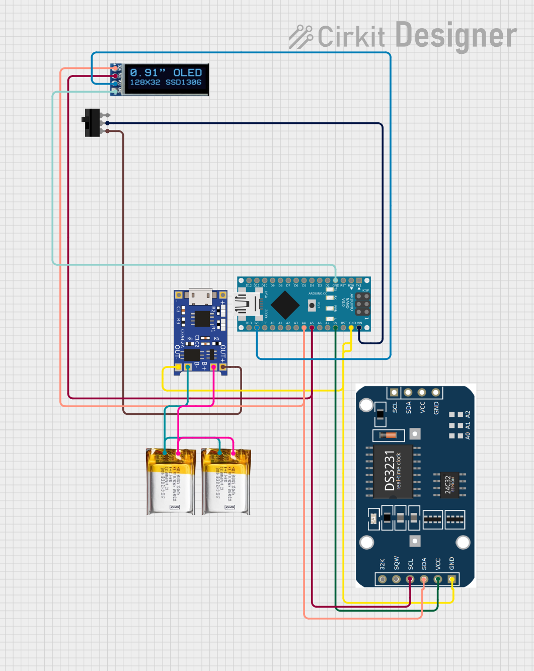

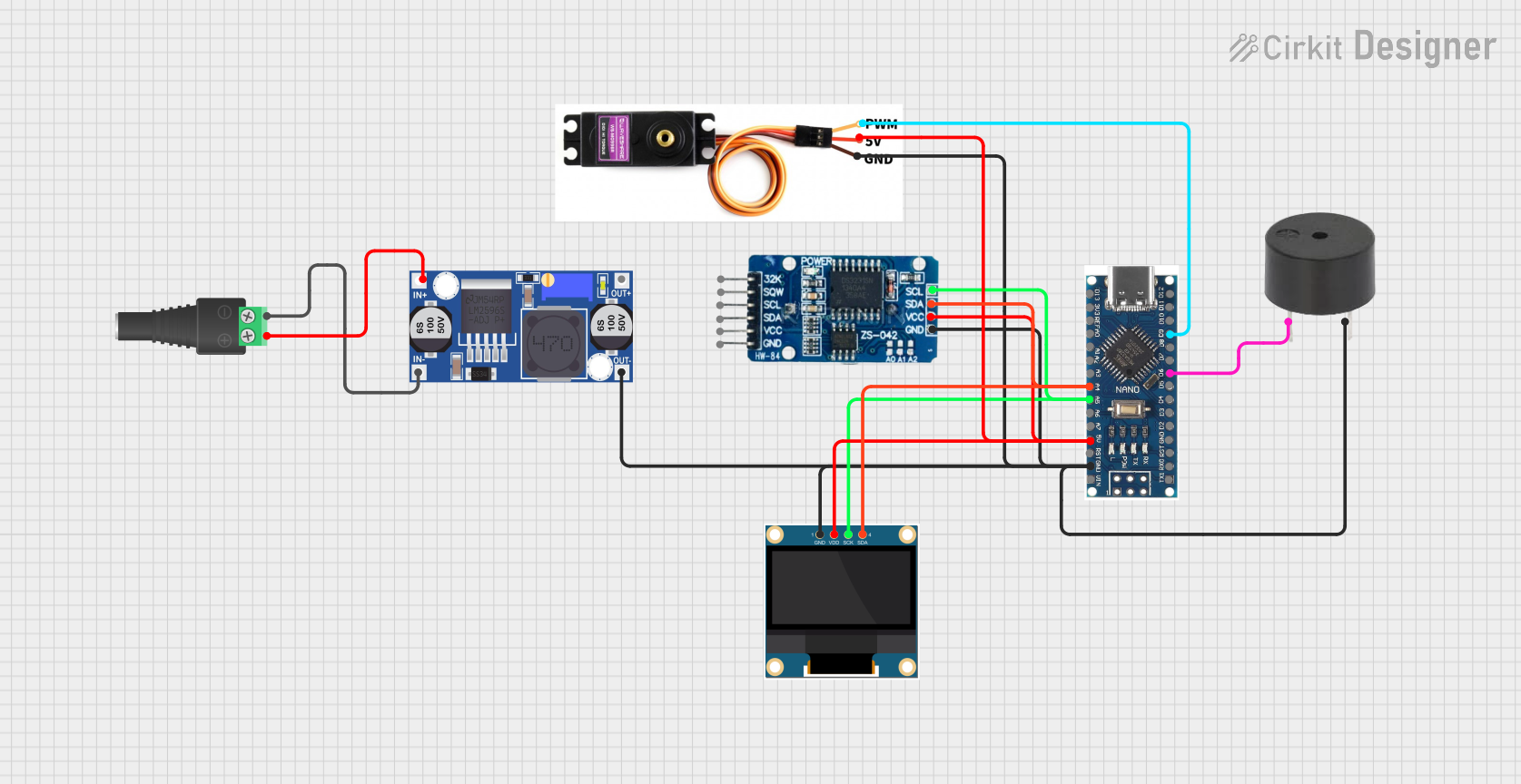
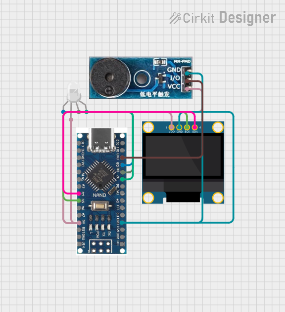
Explore Projects Built with Arduino NANO 3 USB-C
Common Applications and Use Cases
- IoT (Internet of Things) devices
- Wearable electronics
- Robotics and automation
- Sensor-based projects
- Educational tools for learning embedded systems
- Compact prototypes requiring USB-C connectivity
Technical Specifications
The following table outlines the key technical details of the Arduino NANO 3 USB-C:
| Parameter | Specification |
|---|---|
| Microcontroller | ATmega328P |
| Operating Voltage | 5V |
| Input Voltage (VIN) | 7-12V |
| Digital I/O Pins | 14 (6 PWM outputs) |
| Analog Input Pins | 8 |
| DC Current per I/O Pin | 40 mA |
| Flash Memory | 32 KB (2 KB used by bootloader) |
| SRAM | 2 KB |
| EEPROM | 1 KB |
| Clock Speed | 16 MHz |
| USB Interface | USB-C |
| Dimensions | 45 mm x 18 mm |
| Weight | 7 g |
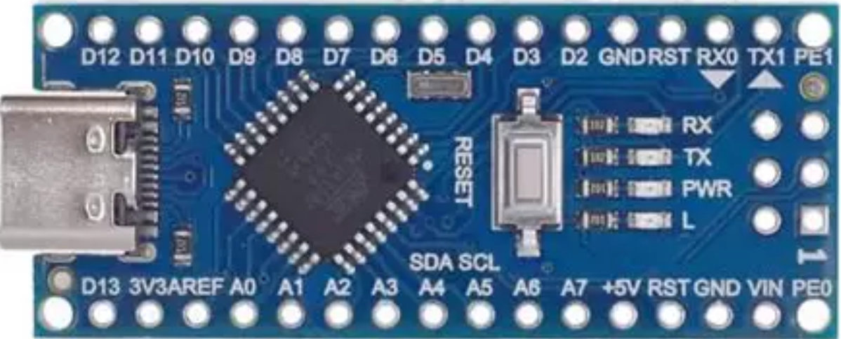
Pin Configuration and Descriptions
The Arduino NANO 3 USB-C has a total of 30 pins. Below is a detailed description of the pin configuration:
| Pin | Type | Description |
|---|---|---|
| VIN | Power Input | External power input (7-12V). |
| GND | Ground | Ground connection. |
| 5V | Power Output | Regulated 5V output. |
| 3.3V | Power Output | Regulated 3.3V output. |
| A0-A7 | Analog Input | Analog input pins (10-bit resolution). |
| D0-D13 | Digital I/O | Digital input/output pins. D3, D5, D6, D9, D10, and D11 support PWM. |
| RX (D0) | Digital Input | UART receive pin. |
| TX (D1) | Digital Output | UART transmit pin. |
| RST | Reset | Resets the microcontroller. |
| USB-C | USB Interface | Used for programming and power. |
Usage Instructions
How to Use the Arduino NANO 3 USB-C in a Circuit
Powering the Board:
- Connect the board to your computer or a USB power source using a USB-C cable.
- Alternatively, supply power through the VIN pin (7-12V) or the 5V pin (regulated 5V).
Programming the Board:
- Install the Arduino IDE from the official Arduino website.
- Connect the board to your computer via USB-C.
- In the Arduino IDE, select Tools > Board > Arduino Nano.
- Under Tools > Processor, select ATmega328P (Old Bootloader).
- Write your code and click the Upload button to program the board.
Connecting Components:
- Use the digital and analog pins to connect sensors, actuators, and other peripherals.
- Ensure that the current drawn by connected components does not exceed the pin's maximum rating (40 mA).
Important Considerations and Best Practices
- Avoid shorting the pins or exceeding the voltage/current ratings to prevent damage.
- Use a proper USB-C cable that supports data transfer for programming.
- If using external power, ensure the voltage is within the recommended range (7-12V).
- For precise analog readings, connect the AREF pin to an external reference voltage.
Example Code for Arduino NANO 3 USB-C
The following example demonstrates how to blink an LED connected to pin D13:
// Blink an LED connected to pin D13
// This example toggles the LED on and off every second.

void setup() {
  pinMode(13, OUTPUT); // Set pin D13 as an output
}

void loop() {
  digitalWrite(13, HIGH); // Turn the LED on
  delay(1000);            // Wait for 1 second
  digitalWrite(13, LOW);  // Turn the LED off
  delay(1000);            // Wait for 1 second
}
Troubleshooting and FAQs
Common Issues and Solutions
The board is not recognized by the computer:
- Ensure you are using a USB-C cable that supports data transfer.
- Check if the correct drivers are installed. Visit the Arduino support page for assistance.
Upload error in the Arduino IDE:
- Verify that the correct board and processor are selected in the Tools menu.
- Ensure no other application is using the COM port.
The board does not power on:
- Check the USB-C connection or external power supply.
- Ensure the power source provides sufficient voltage and current.
Analog readings are inaccurate:
- Use a stable reference voltage on the AREF pin.
- Avoid electrical noise near the analog input pins.
FAQs
Q: Can I power the Arduino NANO 3 USB-C with a battery?
A: Yes, you can power the board using a battery connected to the VIN pin (7-12V) or the 5V pin (regulated 5V).
Q: Is the Arduino NANO 3 USB-C compatible with shields?
A: The board is not directly compatible with standard Arduino shields due to its smaller size, but you can use jumper wires to connect shields.
Q: Can I use the Arduino NANO 3 USB-C for wireless communication?
A: Yes, you can connect wireless modules like Bluetooth or Wi-Fi (e.g., HC-05, ESP8266) to the board via its digital or serial pins.
Q: What is the difference between the Arduino NANO 3 USB-C and the original Arduino Nano?
A: The main difference is the USB-C interface, which replaces the Mini-USB port on the original Nano, providing a more modern and robust connection.