Cirkit Designer Logo
Cirkit Designer
Your all-in-one circuit design IDE
Home / 
Component Documentation

How to Use APA102 LED Strip: Examples, Pinouts, and Specs

Image of APA102 LED Strip
Cirkit Designer LogoDesign with APA102 LED Strip in Cirkit Designer

Introduction

The APA102 LED Strip is a flexible and versatile lighting solution that consists of individually addressable RGB LEDs. Each LED on the strip can be controlled independently, allowing for a wide range of color effects and animations. The APA102 protocol used for communication is fast and supports high refresh rates, making it suitable for dynamic lighting displays. Common applications include decorative lighting, signage, and complex lighting sequences for events or installations.

Explore Projects Built with APA102 LED Strip

Use Cirkit Designer to design, explore, and prototype these projects online. Some projects support real-time simulation. Click "Open Project" to start designing instantly!
Arduino-Controlled APA102 LED Strip with Battery Power and Rocker Switch
Image of arduinio: A project utilizing APA102 LED Strip in a practical application
This circuit features an Arduino UNO microcontroller that controls an APA102 LED Strip. The Arduino is powered by a 3xAA battery pack through a rocker switch, which allows for turning the power supply on and off. The LED strip's data and clock inputs are connected to digital pins D11 and D13 of the Arduino, respectively, enabling the microcontroller to program the LED patterns.
Cirkit Designer LogoOpen Project in Cirkit Designer
A-Star 32U4 Mini Controlled LED Strip Lighting
Image of Tira LED: A project utilizing APA102 LED Strip in a practical application
This circuit consists of an A-Star 32U4 Mini microcontroller connected to an LED Strip. The microcontroller provides power (5V) and ground connections to the LED Strip and controls it through two digital pins (12 and 11) for clock (CI) and data input (DI), respectively. The purpose of this circuit is to enable the microcontroller to control the lighting patterns or colors of the LED Strip.
Cirkit Designer LogoOpen Project in Cirkit Designer
RGB LED Strip Color Controller with Potentiometers and Power Switch
Image of potbased decoration: A project utilizing APA102 LED Strip in a practical application
This circuit controls an RGB LED strip using three potentiometers, each potentiometer likely adjusts the intensity of one color channel (red, green, blue) of the LED strip. A rocker switch is used to power the circuit on and off, and an 18650 Li-Ion battery provides the power source. The common connection of the LED strip is connected to the negative terminal of the battery, while the positive terminal goes through the rocker switch to the potentiometers and then to the individual color channels.
Cirkit Designer LogoOpen Project in Cirkit Designer
220V to 12V LED Strip Lighting System
Image of Effect of light on plant growth: A project utilizing APA102 LED Strip in a practical application
This circuit consists of a 220V AC power source connected to an AC-to-DC converter, which steps down the voltage to 12V DC to power a series of three 12V white LED strips. The LED strips are connected in parallel to the output of the converter, sharing a common ground. The circuit is designed to convert household AC voltage to a lower DC voltage suitable for powering LED lighting.
Cirkit Designer LogoOpen Project in Cirkit Designer

Explore Projects Built with APA102 LED Strip

Use Cirkit Designer to design, explore, and prototype these projects online. Some projects support real-time simulation. Click "Open Project" to start designing instantly!
Image of arduinio: A project utilizing APA102 LED Strip in a practical application
Arduino-Controlled APA102 LED Strip with Battery Power and Rocker Switch
This circuit features an Arduino UNO microcontroller that controls an APA102 LED Strip. The Arduino is powered by a 3xAA battery pack through a rocker switch, which allows for turning the power supply on and off. The LED strip's data and clock inputs are connected to digital pins D11 and D13 of the Arduino, respectively, enabling the microcontroller to program the LED patterns.
Cirkit Designer LogoOpen Project in Cirkit Designer
Image of Tira LED: A project utilizing APA102 LED Strip in a practical application
A-Star 32U4 Mini Controlled LED Strip Lighting
This circuit consists of an A-Star 32U4 Mini microcontroller connected to an LED Strip. The microcontroller provides power (5V) and ground connections to the LED Strip and controls it through two digital pins (12 and 11) for clock (CI) and data input (DI), respectively. The purpose of this circuit is to enable the microcontroller to control the lighting patterns or colors of the LED Strip.
Cirkit Designer LogoOpen Project in Cirkit Designer
Image of potbased decoration: A project utilizing APA102 LED Strip in a practical application
RGB LED Strip Color Controller with Potentiometers and Power Switch
This circuit controls an RGB LED strip using three potentiometers, each potentiometer likely adjusts the intensity of one color channel (red, green, blue) of the LED strip. A rocker switch is used to power the circuit on and off, and an 18650 Li-Ion battery provides the power source. The common connection of the LED strip is connected to the negative terminal of the battery, while the positive terminal goes through the rocker switch to the potentiometers and then to the individual color channels.
Cirkit Designer LogoOpen Project in Cirkit Designer
Image of Effect of light on plant growth: A project utilizing APA102 LED Strip in a practical application
220V to 12V LED Strip Lighting System
This circuit consists of a 220V AC power source connected to an AC-to-DC converter, which steps down the voltage to 12V DC to power a series of three 12V white LED strips. The LED strips are connected in parallel to the output of the converter, sharing a common ground. The circuit is designed to convert household AC voltage to a lower DC voltage suitable for powering LED lighting.
Cirkit Designer LogoOpen Project in Cirkit Designer

Technical Specifications

Key Technical Details

  • Voltage: Typically 5V
  • Current: Varies depending on the number of LEDs (approximately 20mA per LED at full brightness)
  • Color Depth: 24-bit color (8 bits per channel)
  • Communication Protocol: SPI-like (two-wire interface: clock and data)
  • Refresh Rate: High (up to thousands of frames per second)
  • Operating Temperature: -25°C to 85°C

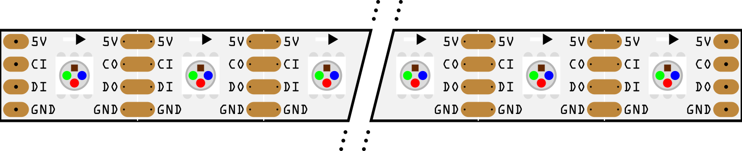
Pin Configuration and Descriptions

Pin Name Description
VCC Power supply (5V)
GND Ground connection
CI Clock input
DI Data input
CO Clock output (for cascading strips)
DO Data output (for cascading strips)

Usage Instructions

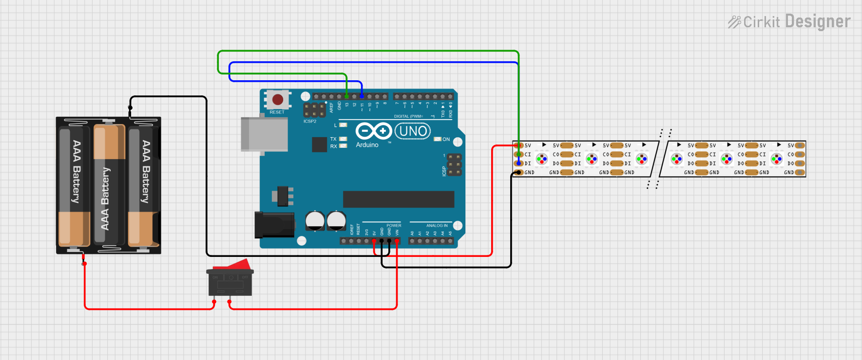
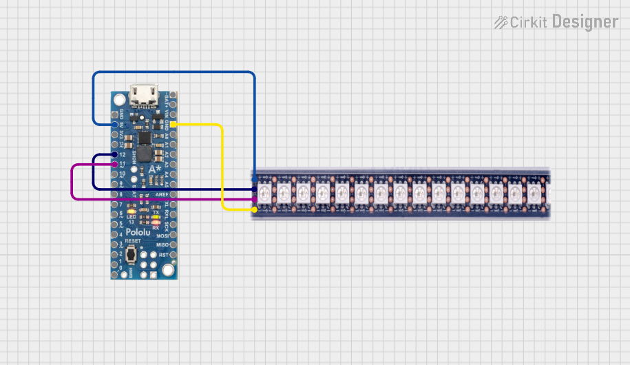
Connecting to a Microcontroller

  1. Connect the VCC pin to a 5V power supply.
  2. Connect the GND pin to the ground on both the power supply and the microcontroller.
  3. Connect the CI (Clock Input) to a digital pin on the microcontroller that supports SPI clock.
  4. Connect the DI (Data Input) to another digital pin that supports SPI MOSI.

Programming the APA102 LED Strip (Arduino Example)

#include <FastLED.h>

#define NUM_LEDS 60 // Number of LEDs in the strip
#define DATA_PIN 7  // Data input pin
#define CLOCK_PIN 14 // Clock input pin

CRGB leds[NUM_LEDS];

void setup() {
  FastLED.addLeds<APA102, DATA_PIN, CLOCK_PIN, BGR>(leds, NUM_LEDS);
}

void loop() {
  // Set the first LED to red
  leds[0] = CRGB::Red;
  FastLED.show();
  delay(500);

  // Set the first LED to green
  leds[0] = CRGB::Green;
  FastLED.show();
  delay(500);

  // Set the first LED to blue
  leds[0] = CRGB::Blue;
  FastLED.show();
  delay(500);
}

Important Considerations and Best Practices

  • Ensure the power supply can handle the current required for the number of LEDs.
  • Use a capacitor (e.g., 1000µF, 6.3V) across the power supply to smooth out power fluctuations.
  • Add a 300 to 500 Ohm resistor on the data input line to prevent voltage spikes.
  • If the strip is long, inject power at multiple points to prevent voltage drop.
  • Always use the correct color ordering (e.g., BGR) when programming the strip.

Troubleshooting and FAQs

Common Issues

  • LEDs not lighting up: Check power supply connections and ensure the microcontroller pins are correctly connected to the data and clock inputs.
  • Flickering LEDs: This may be due to insufficient power or voltage drop along the strip. Ensure power is sufficient and consider power injection at multiple points.
  • Incorrect colors: Verify that the color order in the code matches the strip's requirements (commonly BGR).

Solutions and Tips for Troubleshooting

  • Double-check wiring, especially if extending the strip or cascading multiple strips.
  • Use a logic level converter if the microcontroller operates at 3.3V to match the 5V logic level of the APA102.
  • Keep the clock and data lines as short as possible to prevent signal degradation.
  • Use a multimeter to check for continuity and proper voltage levels along the strip.

FAQs

Q: Can I cut the APA102 LED Strip to a custom length? A: Yes, the strip can be cut at designated points, usually marked with a line and scissors icon.

Q: How do I control multiple strips with one microcontroller? A: You can cascade the strips by connecting the CO and DO of the first strip to the CI and DI of the next strip, respectively.

Q: What library can I use for programming the APA102 with an Arduino? A: The FastLED library is commonly used and provides extensive features for controlling APA102 LEDs.

Q: How do I calculate the power requirement for my APA102 LED Strip? A: Multiply the number of LEDs by the current per LED (typically 20mA at full brightness) and the operating voltage (5V) to get the total power requirement in watts. Always provide a power supply with a higher rating than calculated to ensure stable operation.