How to Use WindDirectionSensor: Examples, Pinouts, and Specs
Introduction
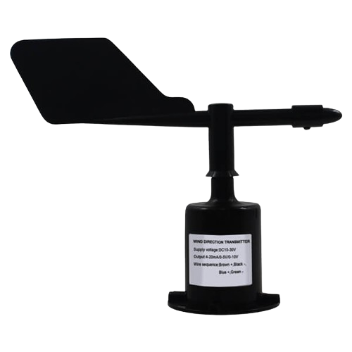
A Wind Direction Sensor is an essential instrument in meteorology and various environmental monitoring applications. It is designed to measure the direction from which the wind is blowing. This sensor typically employs a wind vane, which aligns itself with the wind direction, and an electronic system to convert the vane's position into a readable output, such as degrees or cardinal directions (N, S, E, W). Common applications include weather stations, sailing, and agriculture, where wind direction data is crucial for decision-making.
Explore Projects Built with WindDirectionSensor
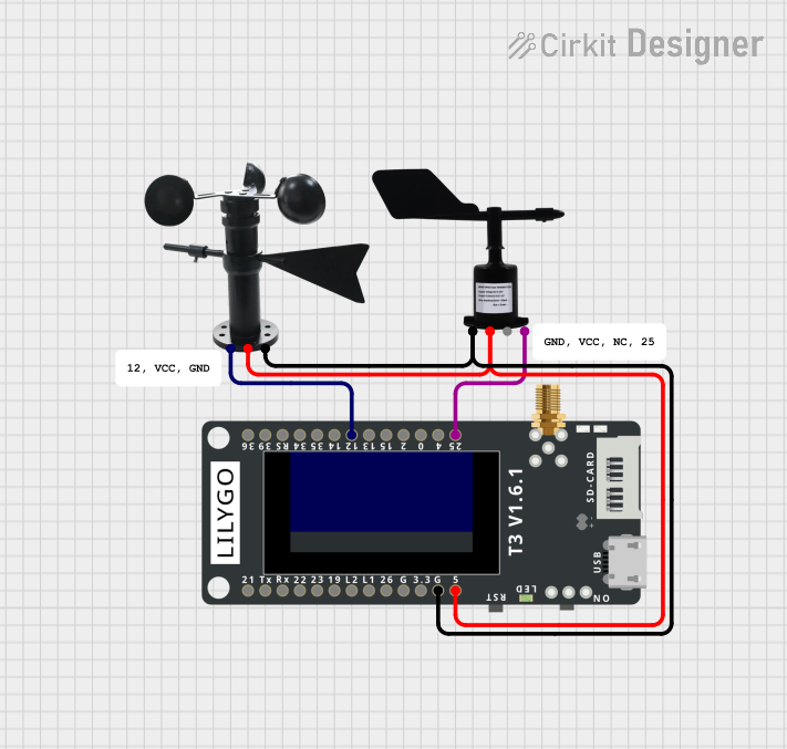
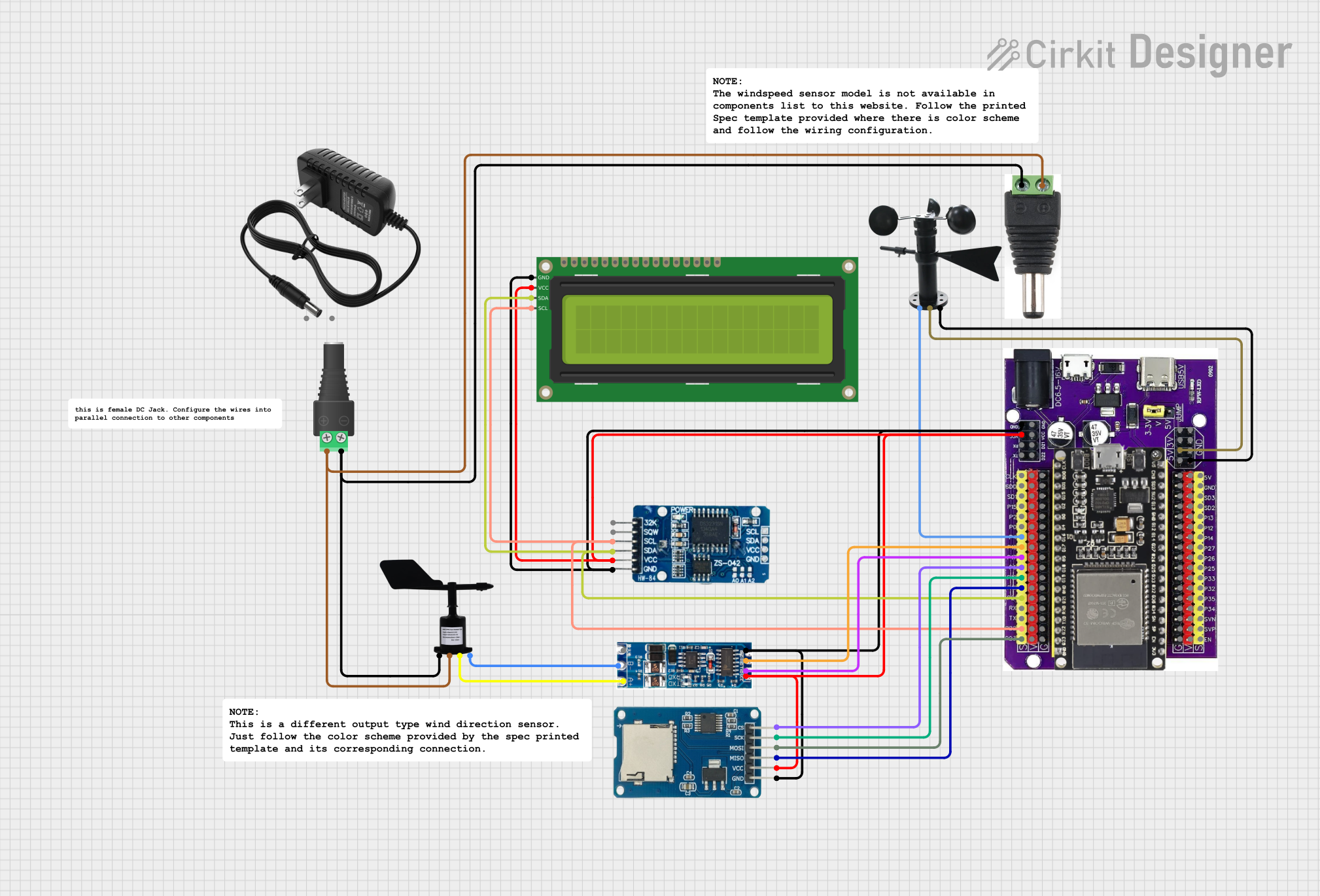
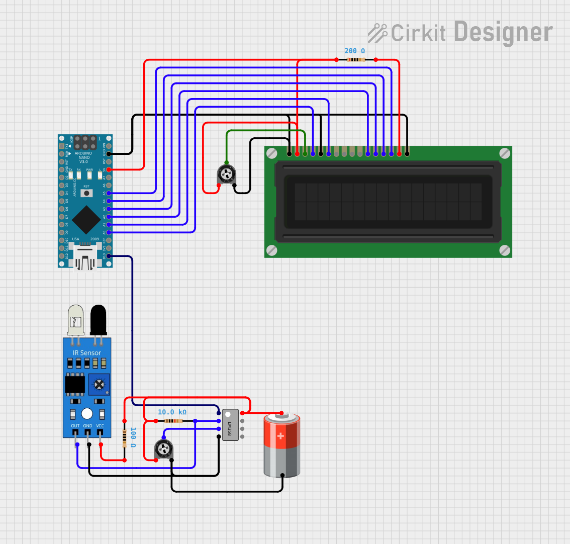
Explore Projects Built with WindDirectionSensor
Technical Specifications
Key Technical Details
- Measurement Range: 0-360 degrees
- Output: Analog voltage corresponding to wind direction
- Accuracy: ±5 degrees
- Resolution: 1 degree
- Operating Voltage: 5V DC
- Current Consumption: 10-20 mA
Pin Configuration and Descriptions
| Pin Number | Description | Notes |
|---|---|---|
| 1 | Analog Output | Connect to analog input on MCU |
| 2 | Power Supply (Vcc) | Connect to 5V power source |
| 3 | Ground (GND) | Connect to ground |
Usage Instructions
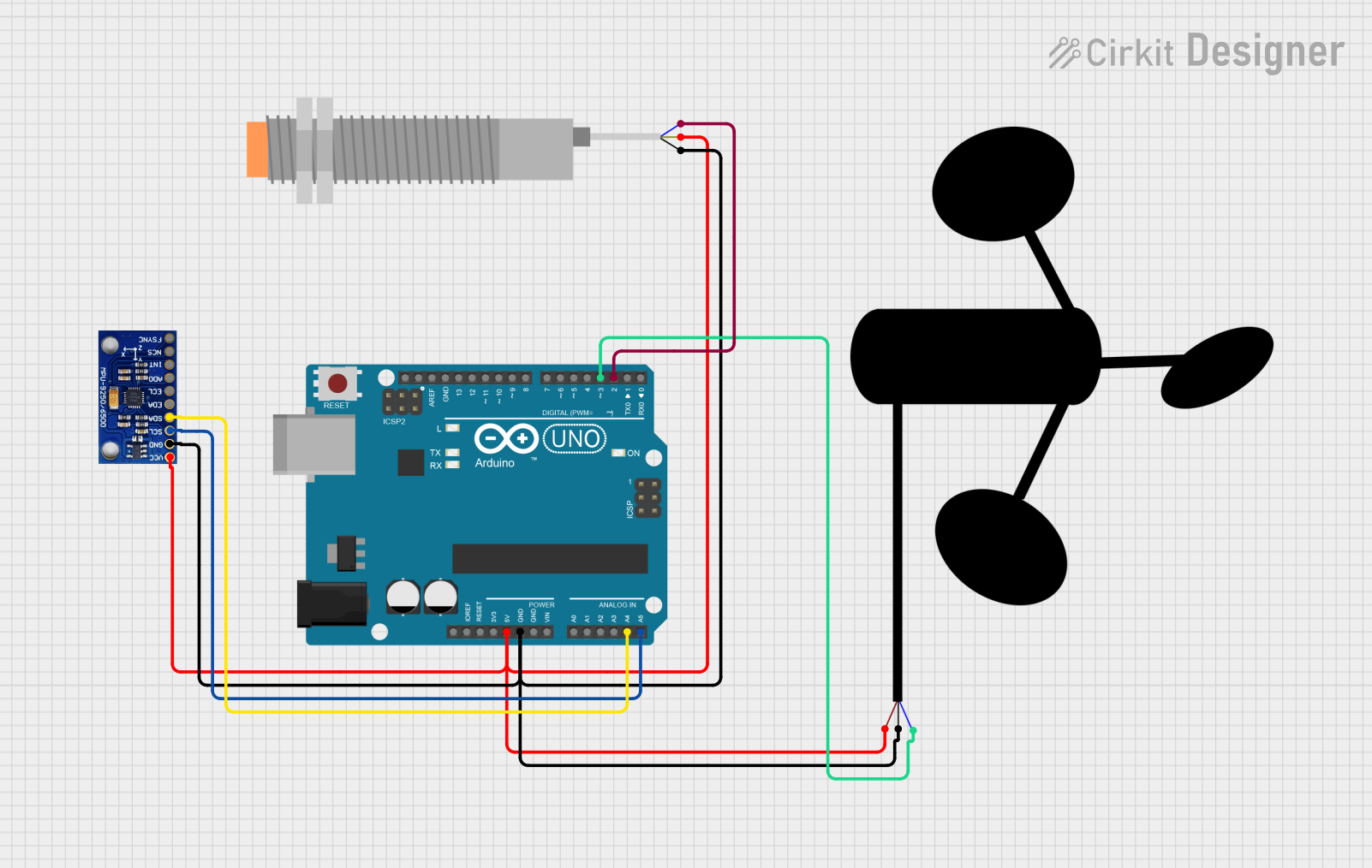
Integration with a Circuit
- Connect the Vcc pin of the Wind Direction Sensor to a 5V power supply.
- Connect the GND pin to the ground of the power supply and the microcontroller unit (MCU).
- Connect the Analog Output pin to an analog input pin on the MCU (e.g., A0 on an Arduino UNO).
Calibration and Reading
- Before taking measurements, calibrate the sensor to ensure accurate readings.
- Use the analog-to-digital converter (ADC) of the MCU to read the analog voltage from the sensor.
- Map the voltage readings to corresponding wind directions (0-360 degrees).
Best Practices
- Mount the sensor at a height and location free from obstructions for accurate wind direction measurement.
- Protect the electronic components from harsh weather conditions.
- Regularly check and maintain the mechanical parts of the wind vane for smooth operation.
Example Code for Arduino UNO
// Define the analog pin connected to the sensor
const int windDirectionPin = A0;

void setup() {
  // Initialize serial communication at 9600 baud rate
  Serial.begin(9600);
}

void loop() {
  // Read the analog value from the wind direction sensor
  int sensorValue = analogRead(windDirectionPin);

  // Convert the analog value to wind direction in degrees
  int windDirection = map(sensorValue, 0, 1023, 0, 360);

  // Print the wind direction to the Serial Monitor
  Serial.print("Wind Direction: ");
  Serial.print(windDirection);
  Serial.println(" degrees");

  // Wait for a second before taking the next reading
  delay(1000);
}
Troubleshooting and FAQs
Common Issues
- Inaccurate Readings: Ensure the sensor is properly calibrated and free from obstructions.
- No Output: Check all connections, ensure the power supply is at 5V, and the sensor is grounded correctly.
- Erratic Readings: Verify that the wind vane moves freely without any mechanical hindrance.
Solutions and Tips
- If the readings are consistently inaccurate, recalibrate the sensor and check for any physical damage.
- In case of no output, inspect the wiring for any loose connections or breaks.
- For erratic readings, lubricate the mechanical parts if necessary and ensure the sensor is mounted securely.
FAQs
Q: Can the sensor be used in heavy rain? A: While the sensor is designed for outdoor use, it should be protected from direct exposure to water to prevent damage.
Q: How often should the sensor be calibrated? A: Calibration should be done upon installation and periodically checked, especially after exposure to severe weather conditions.
Q: What is the maximum cable length for the sensor? A: To avoid signal degradation, keep the cable length as short as possible, preferably under 10 meters.
Note: The information provided in this documentation is based on a generic Wind Direction Sensor and may vary for specific models. Always refer to the manufacturer's datasheet for exact specifications and instructions.