How to Use bno085 9-dof 9-DOF (IMU) sensor module: Examples, Pinouts, and Specs
Introduction
The BNO085 is a high-performance Inertial Measurement Unit (IMU) developed by Adafruit Industries LLC (Manufacturer Part ID: 4754). It integrates a 3-axis accelerometer, 3-axis gyroscope, and 3-axis magnetometer to provide precise orientation and motion tracking. The module leverages advanced sensor fusion algorithms to deliver accurate 9-degree-of-freedom (9-DOF) data, making it a versatile solution for a wide range of applications.
Explore Projects Built with bno085 9-dof 9-DOF (IMU) sensor module


Explore Projects Built with bno085 9-dof 9-DOF (IMU) sensor module
Common Applications and Use Cases
- Robotics: Motion tracking and navigation
- Drones: Stabilization and orientation control
- Augmented Reality (AR): Head tracking and gesture recognition
- Wearable Devices: Activity monitoring and motion sensing
- Gaming: Controller motion tracking
- Industrial Automation: Machine orientation and movement detection
Technical Specifications
The following table outlines the key technical details of the BNO085 sensor module:
| Parameter | Value |
|---|---|
| Manufacturer | Adafruit Industries LLC |
| Manufacturer Part ID | 4754 - Adafruit 9-DOF Orientation IMU Fusion Breakout |
| Sensor Type | 3-axis accelerometer, 3-axis gyroscope, 3-axis magnetometer |
| Operating Voltage | 3.3V to 5V |
| Communication Interfaces | I2C, SPI, UART |
| I2C Address (Default) | 0x4A |
| Operating Temperature Range | -40°C to +85°C |
| Dimensions | 25.4mm x 17.8mm x 3.2mm |
| Weight | 1.5g |
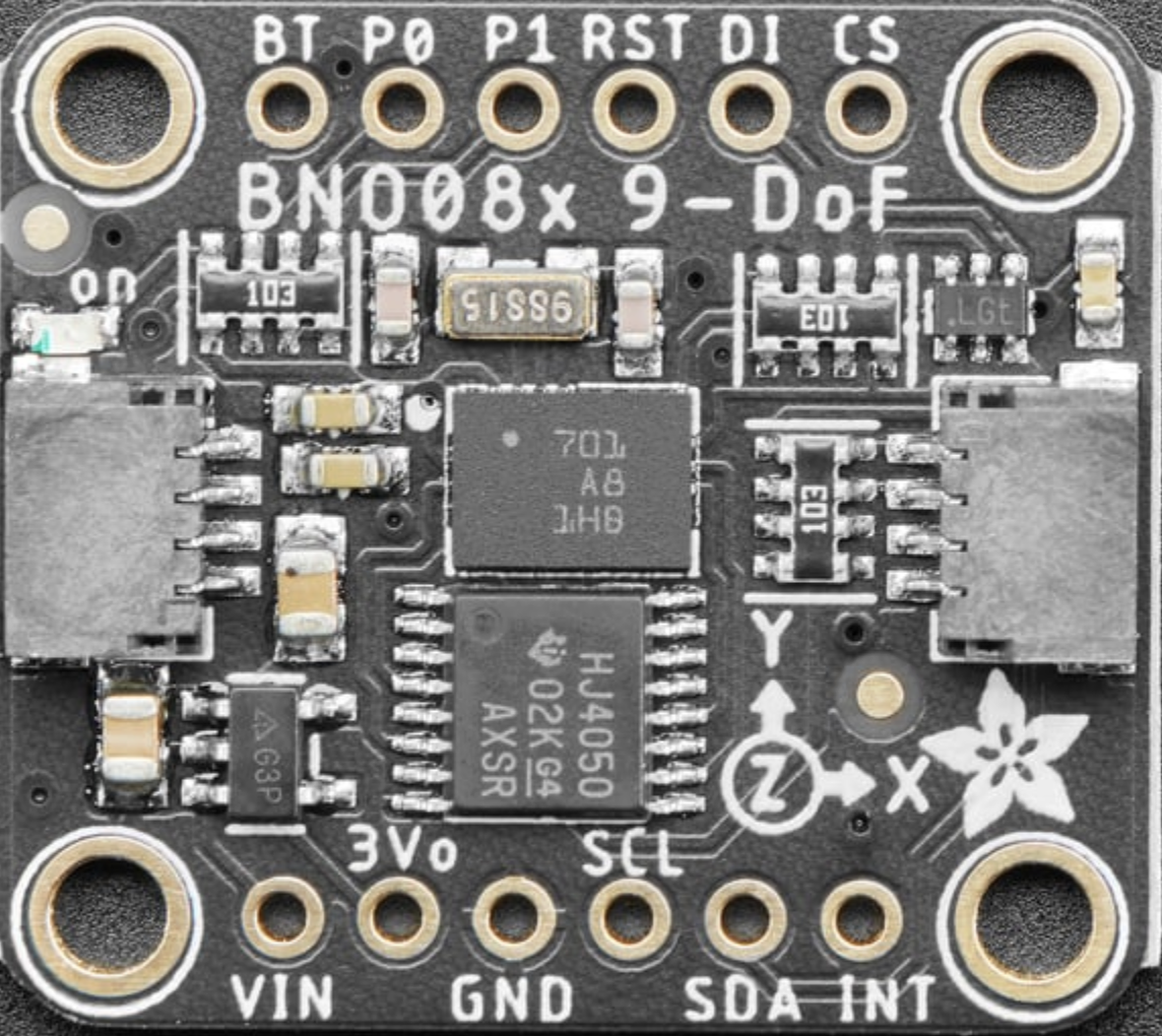
Pin Configuration and Descriptions
The BNO085 breakout board features the following pins:
| Pin Name | Description |
|---|---|
| VIN | Power input (3.3V to 5V) |
| GND | Ground connection |
| SDA | I2C data line |
| SCL | I2C clock line |
| CS | Chip select for SPI communication (active low) |
| SDO | SPI data output (MISO) |
| SDI | SPI data input (MOSI) |
| SCK | SPI clock line |
| INT | Interrupt pin (used for event notifications) |
| RST | Reset pin (active low, optional for resetting the module) |
Usage Instructions
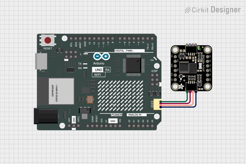
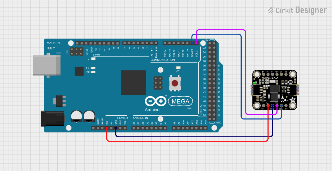
How to Use the BNO085 in a Circuit
- Power the Module: Connect the VIN pin to a 3.3V or 5V power source and the GND pin to ground.
- Choose a Communication Interface:
- For I2C: Connect the SDA and SCL pins to the corresponding I2C pins on your microcontroller.
- For SPI: Connect the CS, SDO, SDI, and SCK pins to the respective SPI pins on your microcontroller.
- Optional Connections:
- Connect the INT pin to a GPIO pin on your microcontroller to handle interrupts.
- Use the RST pin to reset the module if needed.
- Install Required Libraries: If using an Arduino, install the Adafruit BNO08x library from the Arduino Library Manager.
- Write Code: Use the provided library functions to initialize the sensor, configure settings, and read data.
Important Considerations and Best Practices
- Power Supply: Ensure the module is powered within the specified voltage range (3.3V to 5V).
- Pull-Up Resistors: If using I2C, ensure pull-up resistors are present on the SDA and SCL lines (typically 4.7kΩ).
- Orientation: Mount the sensor securely and in the correct orientation for accurate readings.
- Calibration: Perform sensor calibration for optimal accuracy, especially for the magnetometer.
- Interrupts: Use the INT pin to handle events efficiently, reducing the need for constant polling.
Example Code for Arduino UNO
Below is an example of how to use the BNO085 with an Arduino UNO via I2C:
#include <Wire.h>
#include <Adafruit_BNO08x.h>

// Create an instance of the BNO085 sensor
Adafruit_BNO08x bno = Adafruit_BNO08x();

// Define the I2C port
#define BNO08X_I2C_ADDRESS 0x4A

void setup() {
  Serial.begin(115200); // Initialize serial communication for debugging
  while (!Serial) delay(10); // Wait for Serial Monitor to open

  Serial.println("Initializing BNO085...");

  // Initialize the BNO085 sensor
  if (!bno.begin_I2C(BNO08X_I2C_ADDRESS)) {
    Serial.println("Failed to initialize BNO085! Check connections.");
    while (1); // Halt execution if initialization fails
  }

  Serial.println("BNO085 initialized successfully!");

  // Enable the accelerometer sensor
  if (!bno.enableReport(BNO08X_REPORT_ACCELEROMETER)) {
    Serial.println("Failed to enable accelerometer report!");
    while (1); // Halt execution if enabling fails
  }

  Serial.println("Accelerometer report enabled.");
}

void loop() {
  // Read accelerometer data
  sensors_event_t accelEvent;
  if (bno.getEvent(&accelEvent, Adafruit_BNO08x::SENSOR_REPORT_ACCELEROMETER)) {
    Serial.print("Accel X: "); Serial.print(accelEvent.acceleration.x);
    Serial.print(" m/s^2, Y: "); Serial.print(accelEvent.acceleration.y);
    Serial.print(" m/s^2, Z: "); Serial.print(accelEvent.acceleration.z);
    Serial.println(" m/s^2");
  }

  delay(100); // Delay for readability
}
Troubleshooting and FAQs
Common Issues and Solutions
Sensor Not Detected:
- Ensure the wiring is correct and matches the selected communication interface (I2C or SPI).
- Verify the I2C address (default: 0x4A) or SPI configuration.
- Check for loose connections or damaged wires.
Incorrect or No Data:
- Perform sensor calibration, especially for the magnetometer.
- Ensure the sensor is mounted securely and in the correct orientation.
- Verify that the correct sensor reports are enabled in the code.
Module Not Responding:
- Reset the module using the RST pin.
- Ensure the power supply voltage is within the specified range (3.3V to 5V).
FAQs
Q: Can the BNO085 be used with 5V logic microcontrollers?
A: Yes, the BNO085 breakout board includes level-shifting circuitry, making it compatible with both 3.3V and 5V logic.
Q: How do I calibrate the sensor?
A: Calibration can be performed using the Adafruit BNO08x library. Follow the library's documentation for detailed calibration instructions.
Q: What is the maximum data rate for the BNO085?
A: The maximum data rate depends on the specific sensor report and communication interface. Refer to the sensor's datasheet for detailed information.
Q: Can I use multiple BNO085 modules on the same I2C bus?
A: Yes, but you will need to change the I2C address of additional modules. This can be done by modifying the ADDR pin configuration (if available).