How to Use GPS NEO-6M: Examples, Pinouts, and Specs
Introduction
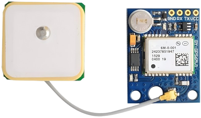
The GPS NEO-6M is a high-performance GPS module designed to provide accurate positioning and timing information. It is widely used in navigation systems, drones, robotics, and other applications requiring precise location tracking. This module features a compact design, low power consumption, and reliable performance, making it an excellent choice for both hobbyists and professionals.
Explore Projects Built with GPS NEO-6M


Explore Projects Built with GPS NEO-6M
Common Applications and Use Cases
- Navigation systems for vehicles and drones
- Robotics requiring location-based functionality
- Geofencing and asset tracking
- Time synchronization for IoT devices
- Outdoor sports and fitness devices
Technical Specifications
The GPS NEO-6M module is built for versatility and ease of integration. Below are its key technical details:
Key Technical Details
| Parameter | Specification |
|---|---|
| Operating Voltage | 2.7V to 3.6V |
| Input Voltage (VCC pin) | 3.3V to 5V |
| Power Consumption | 45mA (typical) |
| Position Accuracy | 2.5 meters CEP |
| Velocity Accuracy | 0.1 m/s |
| Time Accuracy | 30 ns |
| Update Rate | 1 Hz (default), configurable up to 5 Hz |
| Communication Interface | UART (default), SPI |
| Baud Rate (default) | 9600 bps |
| Operating Temperature | -40°C to +85°C |
| Dimensions | 16 x 12.2 x 2.4 mm |
Pin Configuration and Descriptions
The GPS NEO-6M module typically comes with a 4-pin interface. Below is the pinout description:
| Pin Name | Pin Number | Description |
|---|---|---|
| VCC | 1 | Power supply input (3.3V to 5V) |
| GND | 2 | Ground connection |
| TX | 3 | UART Transmit (data output) |
| RX | 4 | UART Receive (data input) |
Usage Instructions
The GPS NEO-6M module is straightforward to use and can be easily integrated into a variety of projects. Below are the steps and best practices for using the module:
Connecting the GPS NEO-6M to an Arduino UNO
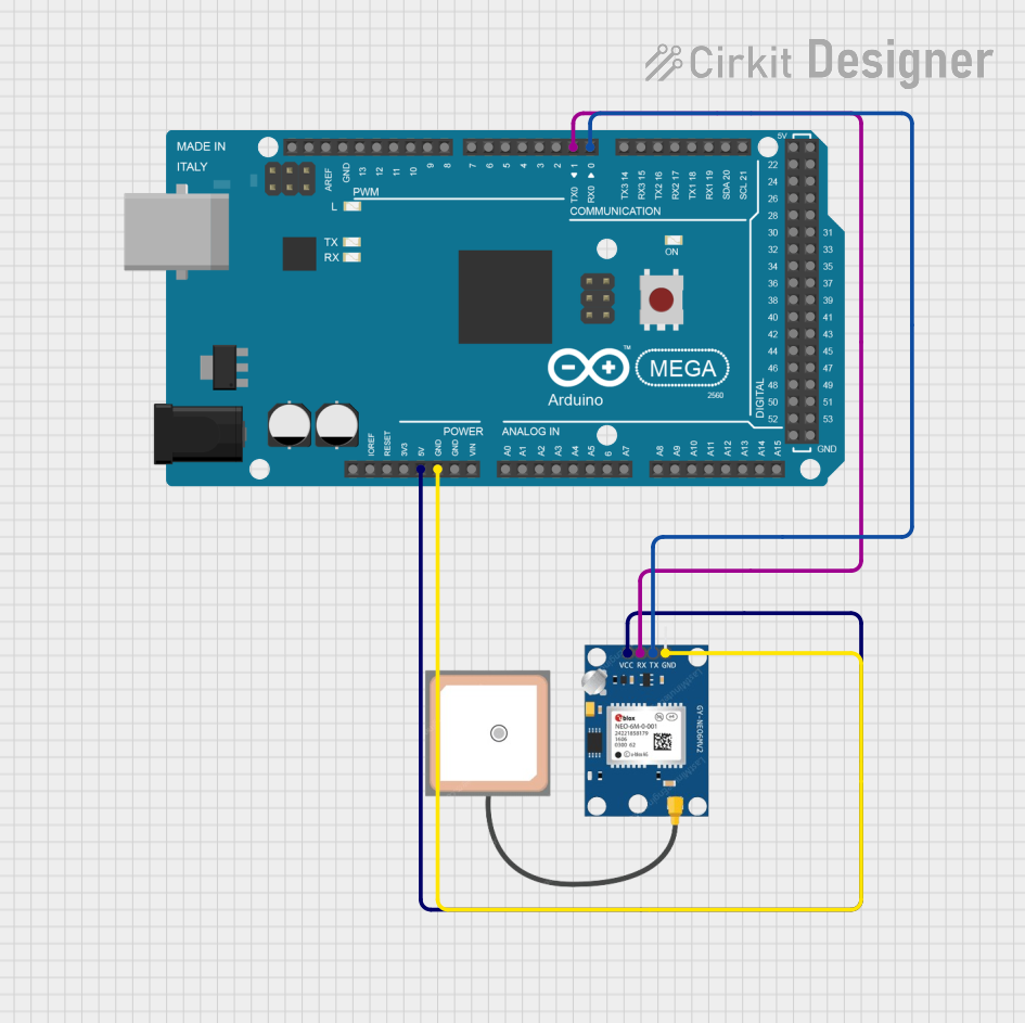
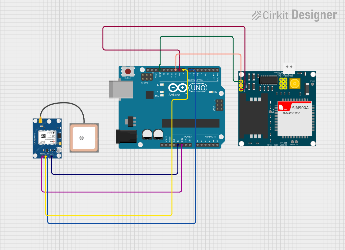
Wiring the Module:
- Connect the
VCCpin of the GPS module to the5Vpin on the Arduino UNO. - Connect the
GNDpin of the GPS module to theGNDpin on the Arduino UNO. - Connect the
TXpin of the GPS module to theRXpin (pin 0) on the Arduino UNO. - Connect the
RXpin of the GPS module to theTXpin (pin 1) on the Arduino UNO.
- Connect the
Install Required Libraries:
- Install the
TinyGPS++library in the Arduino IDE for parsing GPS data. - Install the
SoftwareSeriallibrary if you plan to use software-based serial communication.
- Install the
Sample Code: Below is a sample Arduino sketch to read and display GPS data:
#include <SoftwareSerial.h>
#include <TinyGPS++.h>

// Create a SoftwareSerial instance for GPS communication
SoftwareSerial gpsSerial(4, 3); // RX, TX

// Create a TinyGPS++ object
TinyGPSPlus gps;

void setup() {
  Serial.begin(9600); // Initialize Serial Monitor
  gpsSerial.begin(9600); // Initialize GPS module communication

  Serial.println("GPS NEO-6M Test");
}

void loop() {
  // Read data from the GPS module
  while (gpsSerial.available() > 0) {
    char c = gpsSerial.read();
    // Feed the data into the TinyGPS++ library
    if (gps.encode(c)) {
      // If a valid GPS sentence is received, display the data
      if (gps.location.isUpdated()) {
        Serial.print("Latitude: ");
        Serial.print(gps.location.lat(), 6); // Print latitude
        Serial.print(", Longitude: ");
        Serial.println(gps.location.lng(), 6); // Print longitude
      }
    }
  }
}
Important Considerations and Best Practices
- Antenna Placement: Ensure the GPS antenna has a clear view of the sky for optimal signal reception.
- Power Supply: Use a stable power source to avoid fluctuations that may affect performance.
- Baud Rate: Ensure the baud rate of the GPS module matches the settings in your code.
- Cold Start vs. Warm Start: The module may take longer to acquire a fix during a cold start (first power-up) compared to a warm start (subsequent power-ups).
Troubleshooting and FAQs
Common Issues and Solutions
No GPS Fix (No Latitude/Longitude Data):
- Ensure the antenna has a clear view of the sky.
- Check the power supply and connections.
- Wait for a few minutes, as the module may take time to acquire a fix during a cold start.
Garbage Data on Serial Monitor:
- Verify that the baud rate in the Arduino code matches the GPS module's default baud rate (9600 bps).
- Check for loose or incorrect connections.
Module Not Responding:
- Ensure the
VCCandGNDpins are properly connected. - Confirm that the
TXandRXpins are correctly wired to the Arduino.
- Ensure the
FAQs
Q: Can the GPS NEO-6M work indoors?
A: The GPS NEO-6M is designed for outdoor use and requires a clear view of the sky for optimal performance. It may not work reliably indoors.
Q: How long does it take to get a GPS fix?
A: A cold start may take 30-60 seconds, while a warm start typically takes 1-5 seconds.
Q: Can I use the GPS NEO-6M with a 3.3V microcontroller?
A: Yes, the module supports a 3.3V power supply. Ensure the logic levels of the TX and RX pins are compatible with your microcontroller.
Q: How can I increase the update rate?
A: The update rate can be configured up to 5 Hz using specific NMEA commands. Refer to the module's datasheet for details.