
How to Use LM2577 (TO263): Examples, Pinouts, and Specs
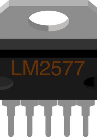
 Design with LM2577 (TO263) in Cirkit Designer
Introduction
The LM2577 is a step-up (boost) voltage regulator manufactured by Texas Instruments. It is designed to convert a lower input voltage into a higher, stable output voltage, making it ideal for applications requiring efficient power conversion. The component can handle loads up to 3A and is available in the TO263 package, which offers excellent thermal management in a compact form factor.
Explore Projects Built with LM2577 (TO263)
 Open Project in Cirkit Designer
 Open Project in Cirkit Designer
 Open Project in Cirkit Designer
 Open Project in Cirkit Designer
Explore Projects Built with LM2577 (TO263)
Open Project in Cirkit DesignerOpen Project in Cirkit DesignerOpen Project in Cirkit DesignerOpen Project in Cirkit DesignerCommon Applications
- Battery-powered devices requiring higher voltage levels
- DC-DC converters for industrial and automotive systems
- Power supplies for LCD displays, sensors, and microcontrollers
- Renewable energy systems, such as solar-powered devices
Technical Specifications
Key Specifications
| Parameter | Value |
|---|---|
| Input Voltage Range | 3.5V to 40V |
| Output Voltage Range | Adjustable (up to 60V) |
| Maximum Output Current | 3A |
| Switching Frequency | 52 kHz |
| Efficiency | Up to 90% |
| Package Type | TO263 |
| Operating Temperature Range | -40°C to +125°C |
Pin Configuration and Descriptions
The LM2577 in the TO263 package has 5 pins. Below is the pinout and description:
| Pin Number | Pin Name | Description |
|---|---|---|
| 1 | VIN | Input voltage pin. Connect to the DC input voltage source. |
| 2 | GND | Ground pin. Connect to the system ground. |
| 3 | VOUT | Output voltage pin. Provides the regulated output voltage. |
| 4 | FB | Feedback pin. Used to set the output voltage via an external resistor divider. |
| 5 | ON/OFF | Enable pin. Logic high enables the regulator; logic low disables it. |
Usage Instructions
How to Use the LM2577 in a Circuit
- Input Voltage: Ensure the input voltage is within the range of 3.5V to 40V.
- Output Voltage Adjustment: Use a resistor divider network connected to the FB pin to set the desired output voltage. The formula for the output voltage is: [ V_{OUT} = V_{REF} \times \left(1 + \frac{R_1}{R_2}\right) ] where ( V_{REF} ) is typically 1.23V.
- Inductor Selection: Choose an inductor with sufficient current rating (greater than 3A) and appropriate inductance value based on the input and output voltage requirements.
- Capacitors: Use low ESR capacitors for input and output filtering to minimize voltage ripple.
- Thermal Management: Ensure proper heat dissipation by mounting the TO263 package on a PCB with adequate copper area or using a heatsink if necessary.
Example Circuit
Below is a basic example of using the LM2577 to step up a 5V input to 12V output:
- Input Voltage (VIN): 5V
- Output Voltage (VOUT): 12V
- Inductor: 100 µH
- Input Capacitor: 470 µF
- Output Capacitor: 220 µF
Arduino UNO Example Code
The LM2577 can be used to power an Arduino UNO or other microcontrollers. Below is an example code to monitor the output voltage using the Arduino's ADC:
// LM2577 Output Voltage Monitoring Example
// This code reads the output voltage of the LM2577 using an analog pin
// and displays the voltage on the Serial Monitor.

const int voltagePin = A0; // Connect the LM2577 output to this pin via a voltage divider
const float referenceVoltage = 5.0; // Arduino ADC reference voltage (5V for UNO)
const int adcResolution = 1024; // 10-bit ADC resolution
const float resistorRatio = 5.0; // Adjust based on your resistor divider (e.g., R1/R2 = 4:1)

void setup() {
  Serial.begin(9600); // Initialize Serial communication
}

void loop() {
  int adcValue = analogRead(voltagePin); // Read the ADC value
  float outputVoltage = (adcValue * referenceVoltage / adcResolution) * resistorRatio;

  // Print the output voltage to the Serial Monitor
  Serial.print("Output Voltage: ");
  Serial.print(outputVoltage);
  Serial.println(" V");

  delay(1000); // Wait for 1 second before the next reading
}
Important Considerations
- Startup Current: Ensure the input power source can handle the inrush current during startup.
- Feedback Resistors: Use precision resistors for the feedback network to maintain accurate output voltage.
- PCB Layout: Minimize the trace length between the input/output capacitors and the LM2577 to reduce noise and improve stability.
Troubleshooting and FAQs
Common Issues and Solutions
| Issue | Possible Cause | Solution |
|---|---|---|
| Output voltage is unstable | Insufficient input/output filtering | Use low ESR capacitors with higher capacitance values. |
| Component overheating | Excessive load current or poor thermal dissipation | Reduce the load or improve heat sinking. |
| No output voltage | Incorrect pin connections or damaged component | Verify connections and replace the LM2577 if necessary. |
| Output voltage too low/high | Incorrect feedback resistor values | Recalculate and adjust the resistor divider network. |
FAQs
Can the LM2577 be used for negative voltage outputs?
No, the LM2577 is designed for step-up (boost) applications and cannot generate negative voltages.What is the maximum output voltage?
The LM2577 can output up to 60V, but ensure the input voltage and component ratings are within safe limits.How do I calculate the inductor value?
The inductor value depends on the input voltage, output voltage, switching frequency, and load current. Refer to the LM2577 datasheet for detailed calculations.Can I use the LM2577 with a battery?
Yes, the LM2577 is suitable for battery-powered applications, provided the input voltage is within the specified range.
By following this documentation, you can effectively integrate the LM2577 into your designs for efficient and reliable voltage boosting.