Cirkit Designer Logo
Cirkit Designer
Your all-in-one circuit design IDE
Home / 
Component Documentation

How to Use LC filter module 3A/50V: Examples, Pinouts, and Specs

Image of LC filter module 3A/50V
Cirkit Designer LogoDesign with LC filter module 3A/50V in Cirkit Designer

Introduction

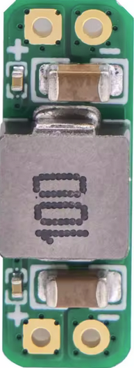
The LC Filter Module 3A/50V (Manufacturer Part ID: LC Filter Module 3A 5-30V) is a compact and efficient electronic component designed to filter out unwanted frequencies in electrical signals. By combining inductors (L) and capacitors (C), this module effectively suppresses noise and ripple, ensuring clean and stable power or signal delivery.

This module is rated for a maximum current of 3A and a voltage of up to 50V, making it suitable for a wide range of applications, including:

  • Power supply noise filtering
  • DC-DC converter ripple suppression
  • Audio signal processing
  • Motor drive noise reduction
  • General-purpose signal conditioning

Explore Projects Built with LC filter module 3A/50V

Use Cirkit Designer to design, explore, and prototype these projects online. Some projects support real-time simulation. Click "Open Project" to start designing instantly!
ESP32-Based Smart Energy Monitoring and Control System
Image of SMART SOCKET: A project utilizing LC filter module 3A/50V in a practical application
This circuit is designed to monitor AC voltage and current using ZMPT101B and ZMCT103C sensors, respectively, with an ESP32 microcontroller processing the sensor outputs. The XL4015 step-down module regulates the power supply to provide a stable voltage to the sensors, the ESP32, and an LCD I2C display. The ESP32 controls a 4-channel relay module for switching AC loads, and the system's operation can be interacted with via the LCD display and a push switch.
Cirkit Designer LogoOpen Project in Cirkit Designer
12V UPS System with Dual 18650 Li-ion Battery Backup and Voltage Regulation
Image of Power supply: A project utilizing LC filter module 3A/50V in a practical application
This circuit is designed to provide an uninterruptible power supply (UPS) system with a 12V DC output. It includes a 12V 5A power supply connected to an AC source through a toggle switch, which charges a pair of 18650 Li-ion batteries via a voltage regulator (XL4016). The UPS module ensures a continuous power supply to the load by switching between the power supply and the battery bank.
Cirkit Designer LogoOpen Project in Cirkit Designer
Cellular-Enabled IoT Device with Real-Time Clock and Power Management
Image of LRCM PHASE 2 BASIC: A project utilizing LC filter module 3A/50V in a practical application
This circuit features a LilyGo-SIM7000G module for cellular communication and GPS functionality, interfaced with an RTC DS3231 for real-time clock capabilities. It includes voltage sensing through two voltage sensor modules, and uses an 8-channel opto-coupler for isolating different parts of the circuit. Power management is handled by a buck converter connected to a DC power source and batteries, with a fuse for protection and a rocker switch for on/off control. Additionally, there's an LED for indication purposes.
Cirkit Designer LogoOpen Project in Cirkit Designer
Battery-Powered 18650 Li-ion Charger with USB Output and Adjustable Voltage Regulator
Image of Breadboard: A project utilizing LC filter module 3A/50V in a practical application
This circuit is a battery management and power supply system that uses three 3.7V batteries connected to a 3S 10A Li-ion 18650 Charger Protection Board Module for balanced charging and protection. The system includes a TP4056 Battery Charging Protection Module for additional charging safety, a Step Up Boost Power Converter to regulate and boost the voltage, and a USB regulator to provide a stable 5V output, controlled by a push switch.
Cirkit Designer LogoOpen Project in Cirkit Designer

Explore Projects Built with LC filter module 3A/50V

Use Cirkit Designer to design, explore, and prototype these projects online. Some projects support real-time simulation. Click "Open Project" to start designing instantly!
Image of SMART SOCKET: A project utilizing LC filter module 3A/50V in a practical application
ESP32-Based Smart Energy Monitoring and Control System
This circuit is designed to monitor AC voltage and current using ZMPT101B and ZMCT103C sensors, respectively, with an ESP32 microcontroller processing the sensor outputs. The XL4015 step-down module regulates the power supply to provide a stable voltage to the sensors, the ESP32, and an LCD I2C display. The ESP32 controls a 4-channel relay module for switching AC loads, and the system's operation can be interacted with via the LCD display and a push switch.
Cirkit Designer LogoOpen Project in Cirkit Designer
Image of Power supply: A project utilizing LC filter module 3A/50V in a practical application
12V UPS System with Dual 18650 Li-ion Battery Backup and Voltage Regulation
This circuit is designed to provide an uninterruptible power supply (UPS) system with a 12V DC output. It includes a 12V 5A power supply connected to an AC source through a toggle switch, which charges a pair of 18650 Li-ion batteries via a voltage regulator (XL4016). The UPS module ensures a continuous power supply to the load by switching between the power supply and the battery bank.
Cirkit Designer LogoOpen Project in Cirkit Designer
Image of LRCM PHASE 2 BASIC: A project utilizing LC filter module 3A/50V in a practical application
Cellular-Enabled IoT Device with Real-Time Clock and Power Management
This circuit features a LilyGo-SIM7000G module for cellular communication and GPS functionality, interfaced with an RTC DS3231 for real-time clock capabilities. It includes voltage sensing through two voltage sensor modules, and uses an 8-channel opto-coupler for isolating different parts of the circuit. Power management is handled by a buck converter connected to a DC power source and batteries, with a fuse for protection and a rocker switch for on/off control. Additionally, there's an LED for indication purposes.
Cirkit Designer LogoOpen Project in Cirkit Designer
Image of Breadboard: A project utilizing LC filter module 3A/50V in a practical application
Battery-Powered 18650 Li-ion Charger with USB Output and Adjustable Voltage Regulator
This circuit is a battery management and power supply system that uses three 3.7V batteries connected to a 3S 10A Li-ion 18650 Charger Protection Board Module for balanced charging and protection. The system includes a TP4056 Battery Charging Protection Module for additional charging safety, a Step Up Boost Power Converter to regulate and boost the voltage, and a USB regulator to provide a stable 5V output, controlled by a push switch.
Cirkit Designer LogoOpen Project in Cirkit Designer

Technical Specifications

Below are the key technical details of the LC Filter Module:

Parameter Value
Manufacturer Aliexpress
Part ID LC Filter Module 3A 5-30V
Maximum Current 3A
Voltage Range 5V to 50V
Inductor Value (L) 47 µH
Capacitor Value (C) 220 µF
Operating Temperature -40°C to +85°C
Dimensions 25mm x 15mm x 10mm

Pin Configuration and Descriptions

The LC Filter Module has four pins, as described in the table below:

Pin Name Description
VIN+ Positive input voltage (unfiltered signal)
VIN- Negative input voltage (ground for unfiltered signal)
VOUT+ Positive output voltage (filtered signal)
VOUT- Negative output voltage (ground for filtered signal)

Usage Instructions

How to Use the LC Filter Module in a Circuit

  1. Connect the Input Voltage:

    • Attach the unfiltered DC voltage source to the VIN+ and VIN- pins. Ensure the voltage is within the module's operating range (5V to 50V).
  2. Connect the Output Load:

    • Connect the load (e.g., a motor, microcontroller, or other device) to the VOUT+ and VOUT- pins. The module will provide a filtered, stable voltage to the load.
  3. Verify Connections:

    • Double-check all connections to ensure proper polarity and avoid short circuits.
  4. Power On:

    • Power on the circuit and measure the output voltage to confirm that the filtering is working as expected.

Important Considerations and Best Practices

  • Current Limit: Ensure the load does not exceed the module's maximum current rating of 3A. Exceeding this limit may damage the module.
  • Voltage Range: Operate the module within the specified voltage range (5V to 50V) to prevent damage to the components.
  • Placement in Circuit: Place the LC filter module as close as possible to the load to minimize noise pickup between the filter and the load.
  • Heat Dissipation: If operating near the maximum current rating, ensure adequate ventilation or heat dissipation to prevent overheating.

Example: Using the LC Filter Module with an Arduino UNO

The LC Filter Module can be used to provide a clean power supply to an Arduino UNO. Below is an example circuit and code:

Circuit Setup

  1. Connect a 12V DC power supply to the VIN+ and VIN- pins of the LC Filter Module.
  2. Connect the VOUT+ and VOUT- pins to the Arduino UNO's VIN and GND pins, respectively.
  3. Ensure the connections are secure and the polarity is correct.

Example Code

// Example code to demonstrate Arduino functionality with an LC Filter Module
// This code blinks an LED connected to pin 13 of the Arduino UNO

void setup() {
  pinMode(13, OUTPUT); // Set pin 13 as an output for the LED
}

void loop() {
  digitalWrite(13, HIGH); // Turn the LED on
  delay(1000);            // Wait for 1 second
  digitalWrite(13, LOW);  // Turn the LED off
  delay(1000);            // Wait for 1 second
}

Troubleshooting and FAQs

Common Issues and Solutions

  1. No Output Voltage:

    • Cause: Incorrect wiring or reversed polarity.
    • Solution: Verify the connections and ensure the input voltage is applied to the correct pins (VIN+ and VIN-).
  2. Excessive Heat:

    • Cause: Load current exceeds the 3A limit or insufficient ventilation.
    • Solution: Reduce the load current or improve heat dissipation by adding a heatsink or increasing airflow.
  3. Insufficient Filtering:

    • Cause: High-frequency noise beyond the module's filtering capability.
    • Solution: Add additional filtering stages or use a module with higher inductance and capacitance values.
  4. Module Damage:

    • Cause: Input voltage exceeds 50V or reverse polarity applied.
    • Solution: Replace the module and ensure the input voltage and polarity are within specifications.

FAQs

Q: Can this module be used with AC signals?
A: No, the LC Filter Module is designed for DC signals only. Using it with AC signals may result in improper operation or damage.

Q: Can I use this module with a 24V power supply?
A: Yes, the module supports input voltages between 5V and 50V, so a 24V power supply is within the acceptable range.

Q: How do I know if the module is working?
A: Measure the output voltage with a multimeter. A stable and clean voltage indicates proper operation.

Q: Can I use this module for audio signal filtering?
A: While primarily designed for power supply filtering, the module can be used for low-frequency audio signal filtering. However, its performance may vary depending on the specific application.

By following this documentation, users can effectively integrate the LC Filter Module 3A/50V into their projects for improved signal and power quality.