How to Use LED Dimmer: Examples, Pinouts, and Specs
Introduction
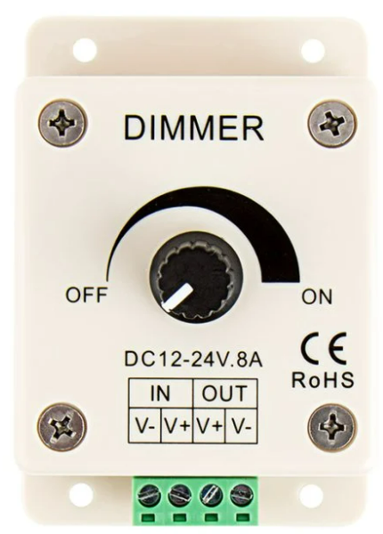
The LED Dimmer (Model: LDK-8A), manufactured by Super Bright LEDs, is a versatile device designed to adjust the brightness of LED lights. By varying the voltage or current supplied to the LEDs, this dimmer allows users to achieve the desired lighting intensity for various applications. It is compact, efficient, and easy to integrate into LED lighting systems.
Explore Projects Built with LED Dimmer

Explore Projects Built with LED Dimmer
Common Applications and Use Cases
- Residential and commercial lighting systems
- Decorative and ambient lighting
- Automotive LED lighting
- Stage and event lighting
- Energy-saving lighting solutions
Technical Specifications
The following table outlines the key technical details of the LDK-8A LED Dimmer:
| Parameter | Specification |
|---|---|
| Manufacturer | Super Bright LEDs |
| Part ID | LDK-8A |
| Input Voltage Range | 12V - 24V DC |
| Maximum Output Current | 8A |
| Power Rating | Up to 192W (at 24V) |
| Dimming Range | 0% - 100% |
| Control Type | Rotary knob |
| Operating Temperature | -20°C to 60°C |
| Dimensions | 89mm x 59mm x 35mm |
| Weight | 75g |
Pin Configuration and Descriptions
The LDK-8A LED Dimmer has a simple terminal block for input and output connections. The pin configuration is as follows:
| Pin | Label | Description |
|---|---|---|
| 1 | V+ (Input) | Positive DC input voltage (12V - 24V) |
| 2 | V- (Input) | Negative DC input voltage (Ground) |
| 3 | V+ (Output) | Positive output voltage to LED load |
| 4 | V- (Output) | Negative output voltage to LED load (Ground) |
Usage Instructions
How to Use the LDK-8A in a Circuit
Power Supply Connection:
- Connect a DC power supply (12V or 24V) to the input terminals of the dimmer.
- Ensure the polarity is correct: V+ to the positive terminal and V- to the negative terminal.
LED Load Connection:
- Connect the LED light(s) to the output terminals of the dimmer.
- Match the polarity of the LED load with the output terminals (V+ and V-).
Adjusting Brightness:
- Use the rotary knob on the dimmer to adjust the brightness of the connected LEDs.
- Turning the knob clockwise increases brightness, while turning it counterclockwise decreases brightness.
Important Considerations and Best Practices
- Power Supply Compatibility: Ensure the power supply voltage matches the input voltage range of the dimmer (12V - 24V DC).
- Current Limit: Do not exceed the maximum output current of 8A to avoid damaging the dimmer.
- Heat Dissipation: If operating near the maximum power rating, ensure proper ventilation to prevent overheating.
- Polarity Check: Always double-check the polarity of connections to avoid short circuits or damage to the LEDs and dimmer.
- LED Compatibility: Use the dimmer with dimmable LED lights only.
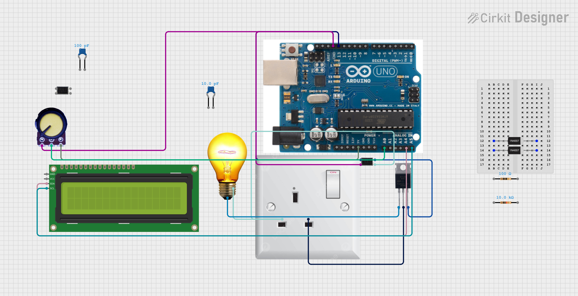
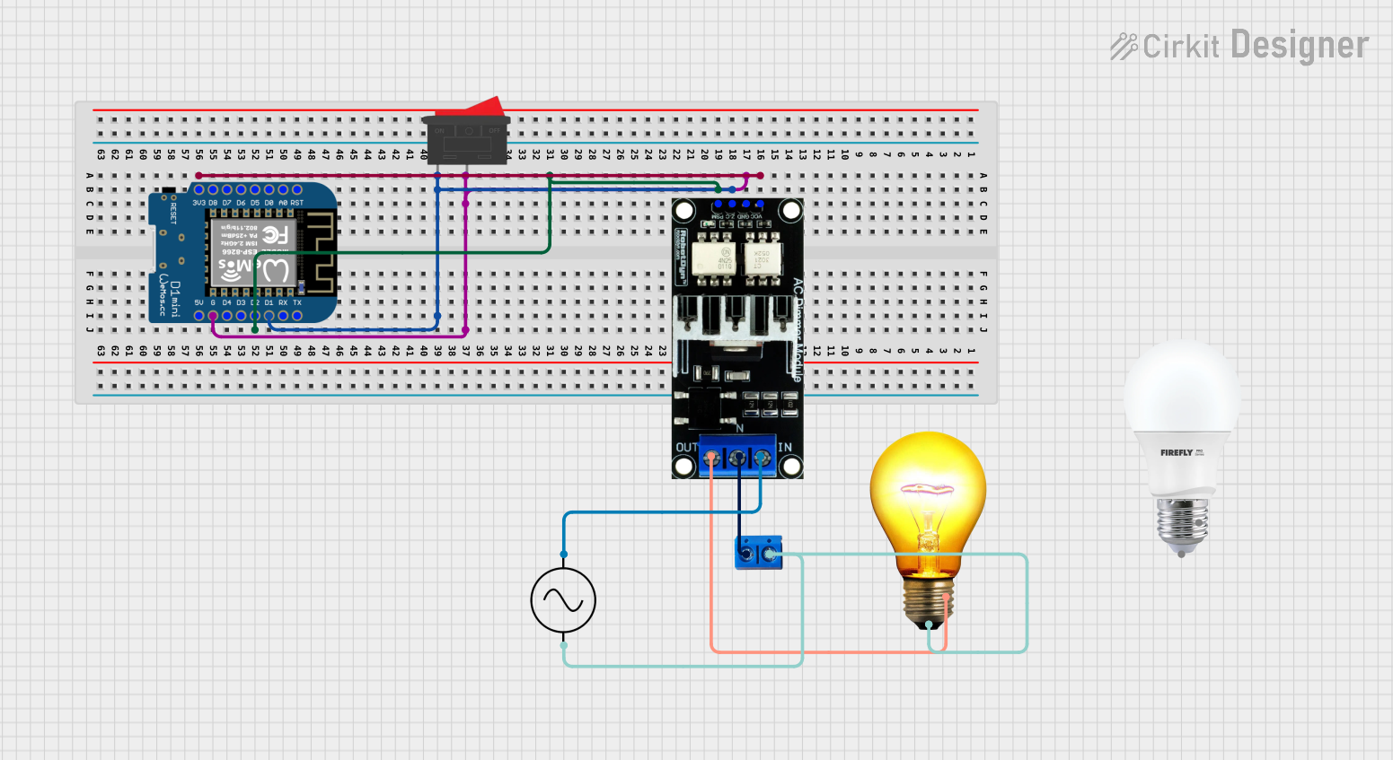
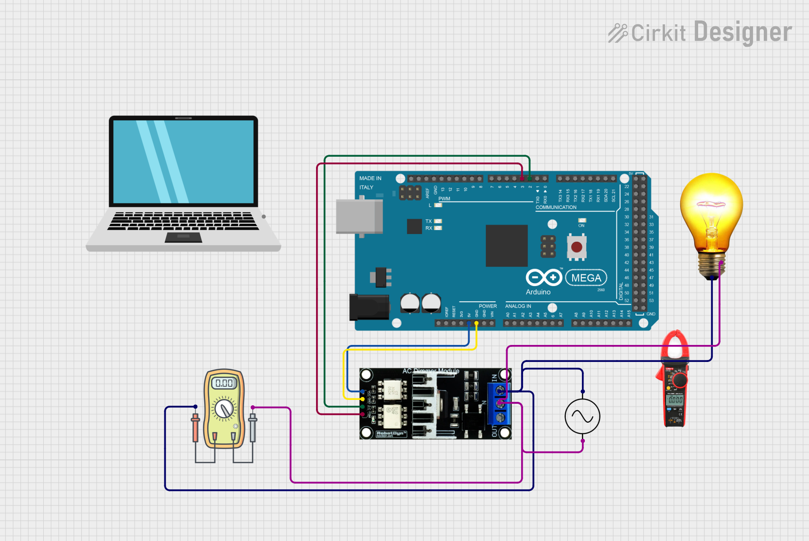
Example: Connecting the LDK-8A to an Arduino UNO
The LDK-8A can be used with an Arduino UNO to control LED brightness programmatically. Below is an example of how to connect and control the dimmer using a PWM signal:
Circuit Setup
- Connect the Arduino's PWM pin (e.g., Pin 9) to the control input of the LDK-8A (if applicable).
- Connect the power supply and LED load as described above.
Arduino Code
// Example code to control LED brightness using PWM and the LDK-8A dimmer
// Connect the Arduino PWM pin (e.g., Pin 9) to the dimmer's control input

const int pwmPin = 9; // PWM pin connected to the dimmer

void setup() {
  pinMode(pwmPin, OUTPUT); // Set the PWM pin as an output
}

void loop() {
  // Gradually increase brightness
  for (int brightness = 0; brightness <= 255; brightness++) {
    analogWrite(pwmPin, brightness); // Write PWM signal to the dimmer
    delay(10); // Small delay for smooth transition
  }

  // Gradually decrease brightness
  for (int brightness = 255; brightness >= 0; brightness--) {
    analogWrite(pwmPin, brightness); // Write PWM signal to the dimmer
    delay(10); // Small delay for smooth transition
  }
}
Troubleshooting and FAQs
Common Issues and Solutions
LEDs Not Lighting Up:
- Cause: Incorrect wiring or polarity.
- Solution: Verify all connections and ensure the polarity matches the input/output terminals.
Flickering LEDs:
- Cause: Incompatible power supply or LED load.
- Solution: Use a stable DC power supply and ensure the LEDs are dimmable.
Dimmer Overheating:
- Cause: Exceeding the maximum current or poor ventilation.
- Solution: Reduce the load or improve airflow around the dimmer.
Brightness Not Changing:
- Cause: Faulty rotary knob or incorrect PWM signal (if using Arduino).
- Solution: Check the rotary knob for damage or verify the PWM signal from the Arduino.
FAQs
Q: Can I use the LDK-8A with non-dimmable LEDs?
A: No, the dimmer is designed for use with dimmable LED lights only.Q: What happens if I exceed the 8A current limit?
A: Exceeding the current limit may damage the dimmer or cause it to overheat. Always stay within the specified limits.Q: Can I use the dimmer with a 5V power supply?
A: No, the dimmer requires a minimum input voltage of 12V DC.Q: Is the dimmer waterproof?
A: No, the LDK-8A is not waterproof. Use it in dry environments only.
This concludes the documentation for the LDK-8A LED Dimmer. For further assistance, refer to the manufacturer's support resources.