How to Use Node MCU ESP32: Examples, Pinouts, and Specs
Introduction
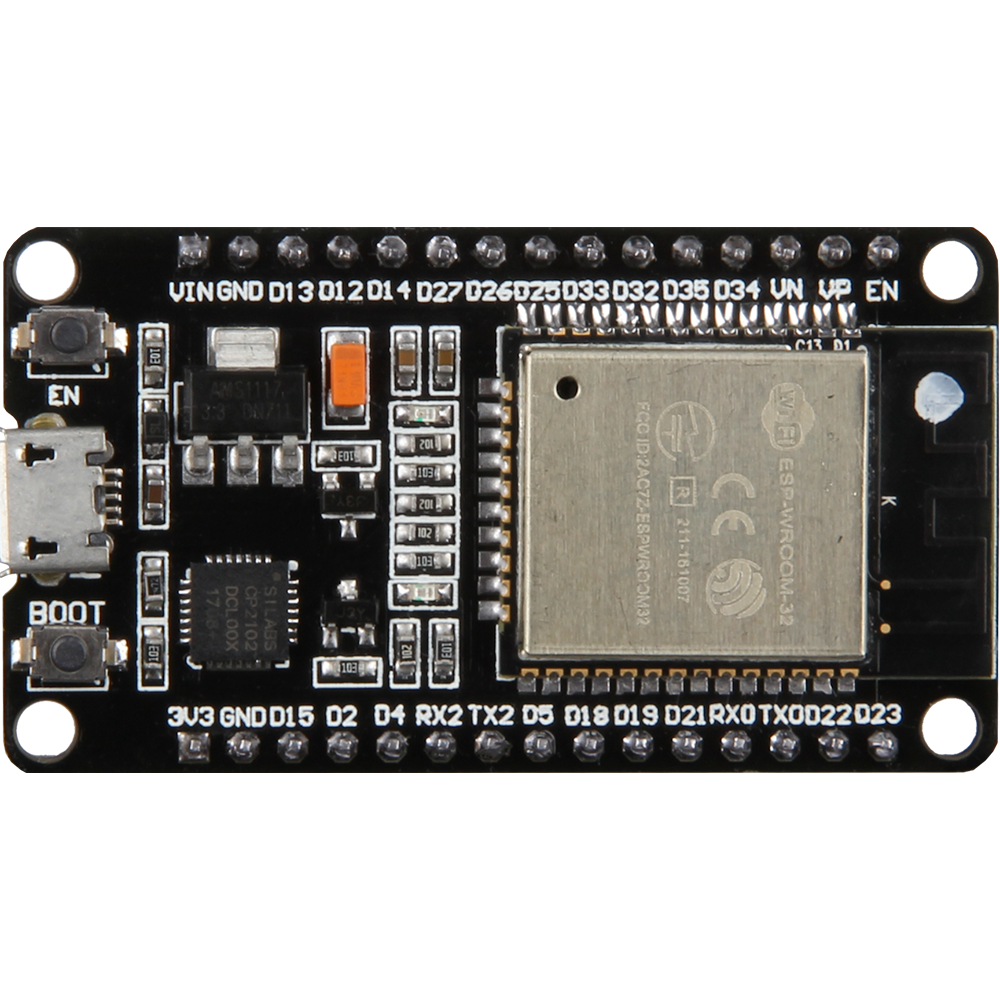
The Node MCU ESP32, manufactured by Espressif Systems (Part ID: ESP-WROOM-32), is a low-cost, open-source IoT platform based on the ESP32 microcontroller. It features integrated Wi-Fi and Bluetooth capabilities, making it an ideal choice for building connected devices and applications. The ESP32 is designed for low-power, high-performance applications, offering dual-core processing, a rich set of peripherals, and extensive connectivity options.
Explore Projects Built with Node MCU ESP32


Explore Projects Built with Node MCU ESP32
Common Applications and Use Cases
- Home automation systems
- IoT devices and smart appliances
- Wireless sensor networks
- Wearable devices
- Industrial automation
- Prototyping and educational projects
Technical Specifications
The Node MCU ESP32 is a versatile microcontroller module with the following key specifications:
General Specifications
| Parameter | Value |
|---|---|
| Microcontroller | ESP32 (dual-core Xtensa LX6 processor) |
| Clock Speed | Up to 240 MHz |
| Flash Memory | 4 MB (varies by model) |
| SRAM | 520 KB |
| Wireless Connectivity | Wi-Fi 802.11 b/g/n, Bluetooth 4.2 (BLE) |
| Operating Voltage | 3.3V |
| Input Voltage (VIN) | 5V (via USB or external power supply) |
| GPIO Pins | 30+ |
| ADC Channels | 18 (12-bit resolution) |
| DAC Channels | 2 (8-bit resolution) |
| Communication Interfaces | UART, SPI, I2C, I2S, CAN, PWM |
| Power Consumption | Ultra-low power modes available |
Pin Configuration and Descriptions
The Node MCU ESP32 features a variety of pins for different functionalities. Below is a summary of the pin configuration:
Power Pins
| Pin Name | Description |
|---|---|
| VIN | Input voltage (5V) |
| 3V3 | 3.3V output |
| GND | Ground |
GPIO Pins
| Pin Name | Description |
|---|---|
| GPIO0 | General-purpose I/O, boot mode |
| GPIO2 | General-purpose I/O |
| GPIO4 | General-purpose I/O |
| GPIO5 | General-purpose I/O |
| GPIO12 | General-purpose I/O |
| GPIO13 | General-purpose I/O |
| GPIO14 | General-purpose I/O |
| GPIO15 | General-purpose I/O |
| GPIO16 | General-purpose I/O |
| GPIO17 | General-purpose I/O |
Communication Pins
| Pin Name | Description |
|---|---|
| TXD0 | UART0 Transmit |
| RXD0 | UART0 Receive |
| SCL | I2C Clock |
| SDA | I2C Data |
| MOSI | SPI Master Out Slave In |
| MISO | SPI Master In Slave Out |
| SCK | SPI Clock |
Analog Pins
| Pin Name | Description |
|---|---|
| ADC1_CH0 | Analog-to-Digital Converter |
| ADC1_CH1 | Analog-to-Digital Converter |
| ADC1_CH2 | Analog-to-Digital Converter |
| ADC1_CH3 | Analog-to-Digital Converter |
Usage Instructions
How to Use the Node MCU ESP32 in a Circuit
- Powering the Module: Connect the VIN pin to a 5V power source or use the micro-USB port for power and programming.
- Programming: Use the Arduino IDE or Espressif's ESP-IDF to write and upload code to the ESP32. Ensure the correct board and COM port are selected in the IDE.
- Connecting Peripherals: Use the GPIO pins to connect sensors, actuators, or other peripherals. Ensure the voltage levels are compatible (3.3V logic).
- Wi-Fi and Bluetooth Setup: Configure the Wi-Fi or Bluetooth settings in your code to enable wireless communication.
Important Considerations and Best Practices
- Voltage Levels: The ESP32 operates at 3.3V logic. Avoid connecting 5V signals directly to GPIO pins.
- Boot Mode: GPIO0 must be pulled low during boot to enter programming mode.
- Power Supply: Use a stable power source to avoid unexpected resets or malfunctions.
- Heat Management: The ESP32 may heat up during operation. Ensure proper ventilation or heat dissipation if used in high-performance applications.
Example Code for Arduino UNO Integration
Below is an example of how to connect the Node MCU ESP32 to a Wi-Fi network using the Arduino IDE:
#include <WiFi.h> // Include the Wi-Fi library

// Replace with your network credentials
const char* ssid = "Your_SSID";
const char* password = "Your_PASSWORD";

void setup() {
  Serial.begin(115200); // Initialize serial communication
  delay(1000);

  // Connect to Wi-Fi
  Serial.println("Connecting to Wi-Fi...");
  WiFi.begin(ssid, password);

  while (WiFi.status() != WL_CONNECTED) {
    delay(500);
    Serial.print("."); // Print dots while connecting
  }

  Serial.println("\nWi-Fi connected!");
  Serial.print("IP Address: ");
  Serial.println(WiFi.localIP()); // Print the assigned IP address
}

void loop() {
  // Add your main code here
}
Troubleshooting and FAQs
Common Issues and Solutions
ESP32 Not Connecting to Wi-Fi
- Ensure the SSID and password are correct.
- Check if the router is within range and supports 2.4 GHz (ESP32 does not support 5 GHz).
Module Not Detected by Computer
- Verify that the correct USB driver is installed (e.g., CP210x or CH340).
- Check the USB cable for data transfer capability (some cables are power-only).
Frequent Resets or Instability
- Use a stable power supply with sufficient current (at least 500 mA).
- Avoid using long or thin wires for power connections.
GPIO Pin Not Responding
- Ensure the pin is not being used for another function (e.g., boot mode).
- Check for short circuits or incorrect wiring.
FAQs
Q: Can the ESP32 operate on battery power?
A: Yes, the ESP32 can be powered by a battery. Use a 3.7V LiPo battery with a voltage regulator to provide 3.3V.
Q: How do I reset the ESP32?
A: Press the onboard reset button or pull the EN pin low momentarily.
Q: Can I use the ESP32 with 5V logic devices?
A: No, the ESP32 operates at 3.3V logic. Use a level shifter to interface with 5V devices.
Q: What is the maximum range of the ESP32's Wi-Fi?
A: The range depends on environmental factors but typically extends up to 100 meters in open spaces.