How to Use LM2596 Buck Converter: Examples, Pinouts, and Specs
Introduction
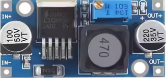
The LM2596 Buck Converter is a step-down voltage regulator designed to efficiently convert a higher input voltage to a lower output voltage. It is widely used in power supply applications due to its high efficiency, compact size, and ease of use. This component is ideal for powering low-voltage devices from higher-voltage sources, such as batteries or unregulated power supplies.
Explore Projects Built with LM2596 Buck Converter


Explore Projects Built with LM2596 Buck Converter
Common Applications
- Powering microcontrollers, sensors, and modules in embedded systems
- Battery-powered devices requiring regulated voltage
- DC-DC voltage conversion in industrial and automotive applications
- LED drivers and portable electronics
Technical Specifications
The LM2596 Buck Converter is available in both fixed and adjustable output voltage versions. Below are the key technical details:
General Specifications
| Parameter | Value |
|---|---|
| Input Voltage Range | 4.5V to 40V |
| Output Voltage Range | 1.23V to 37V (adjustable version) |
| Output Current | Up to 3A |
| Efficiency | Up to 90% |
| Switching Frequency | 150 kHz |
| Operating Temperature Range | -40°C to +125°C |
Pin Configuration
The LM2596 is typically available in a 5-pin TO-220 package. Below is the pinout description:
| Pin Number | Pin Name | Description |
|---|---|---|
| 1 | VIN | Input voltage (4.5V to 40V) |
| 2 | Output | Regulated output voltage |
| 3 | Ground (GND) | Common ground for input and output |
| 4 | Feedback | Voltage feedback for adjustable output version |
| 5 | ON/OFF | Enable/disable pin (optional, not always used) |
Usage Instructions
How to Use the LM2596 in a Circuit
- Connect Input Voltage (VIN): Attach the input voltage source (4.5V to 40V) to the VIN pin. Ensure the input voltage is higher than the desired output voltage.
- Connect Ground (GND): Connect the ground pin to the common ground of the circuit.
- Set Output Voltage (Adjustable Version): For adjustable versions, use a resistor divider network connected to the Feedback pin to set the desired output voltage. The formula is: [ V_{OUT} = V_{REF} \times \left(1 + \frac{R_2}{R_1}\right) ] where ( V_{REF} ) is typically 1.23V.
- Connect Load: Attach the load to the Output pin. Ensure the load does not exceed the maximum current rating (3A).
- Optional ON/OFF Control: If the ON/OFF pin is available, connect it to a logic signal to enable or disable the regulator.
Important Considerations
- Input Capacitor: Place a low-ESR capacitor (e.g., 100 µF) close to the VIN pin to stabilize the input voltage.
- Output Capacitor: Use a low-ESR capacitor (e.g., 220 µF) at the output to reduce voltage ripple.
- Inductor Selection: Choose an inductor with a current rating higher than the maximum load current and an appropriate value to minimize ripple.
- Heat Dissipation: The LM2596 can generate heat under high loads. Use a heatsink or ensure proper ventilation to prevent overheating.
- Avoid Overloading: Do not exceed the maximum current rating of 3A to prevent damage to the component.
Example: Using LM2596 with Arduino UNO
The LM2596 can be used to power an Arduino UNO from a higher voltage source (e.g., a 12V battery). Below is an example circuit and Arduino code to read a sensor powered by the LM2596.
Circuit Connections
- Connect the 12V battery to the VIN pin of the LM2596.
- Set the LM2596 output to 5V using the onboard potentiometer or resistor divider.
- Connect the LM2596 output to the Arduino UNO's 5V pin and GND to GND.
- Power a sensor (e.g., DHT11) from the Arduino's 5V pin.
Arduino Code
#include <DHT.h>

// Define the DHT sensor pin and type
#define DHTPIN 2       // DHT sensor connected to digital pin 2
#define DHTTYPE DHT11  // DHT11 sensor type

DHT dht(DHTPIN, DHTTYPE);

void setup() {
  Serial.begin(9600);  // Initialize serial communication
  dht.begin();         // Initialize the DHT sensor
  Serial.println("DHT11 Sensor Test");
}

void loop() {
  delay(2000);  // Wait 2 seconds between readings

  float humidity = dht.readHumidity();    // Read humidity
  float temperature = dht.readTemperature(); // Read temperature in Celsius

  // Check if readings are valid
  if (isnan(humidity) || isnan(temperature)) {
    Serial.println("Failed to read from DHT sensor!");
    return;
  }

  // Print the results to the Serial Monitor
  Serial.print("Humidity: ");
  Serial.print(humidity);
  Serial.print(" %\t");
  Serial.print("Temperature: ");
  Serial.print(temperature);
  Serial.println(" °C");
}
Troubleshooting and FAQs
Common Issues
No Output Voltage:
- Ensure the input voltage is within the specified range (4.5V to 40V).
- Check for proper connections and polarity.
- Verify that the ON/OFF pin is enabled (if applicable).
Output Voltage is Incorrect:
- For adjustable versions, check the resistor divider network.
- Ensure the potentiometer is correctly adjusted for fixed-output modules.
Excessive Heat:
- Verify that the load current does not exceed 3A.
- Use a heatsink or improve ventilation.
High Output Ripple:
- Check the output capacitor and replace it with a low-ESR capacitor if necessary.
- Ensure the inductor value is appropriate for the load.
FAQs
Q: Can the LM2596 be used for AC voltage conversion?
A: No, the LM2596 is a DC-DC converter and cannot directly handle AC voltage. Use a rectifier and filter circuit to convert AC to DC before using the LM2596.
Q: What is the efficiency of the LM2596?
A: The efficiency can reach up to 90%, depending on the input voltage, output voltage, and load conditions.
Q: Can I use the LM2596 to power a Raspberry Pi?
A: Yes, but ensure the output voltage is set to 5V and the current requirement of the Raspberry Pi (including peripherals) does not exceed 3A.
Q: How do I calculate the resistor values for the adjustable version?
A: Use the formula ( V_{OUT} = V_{REF} \times (1 + R_2 / R_1) ), where ( V_{REF} ) is 1.23V. Select ( R_1 ) and ( R_2 ) to achieve the desired output voltage.
This concludes the LM2596 Buck Converter documentation.