
How to Use Adafruit GPIO Expander Bonnet - 16 Additional I/O over I2C: Examples, Pinouts, and Specs
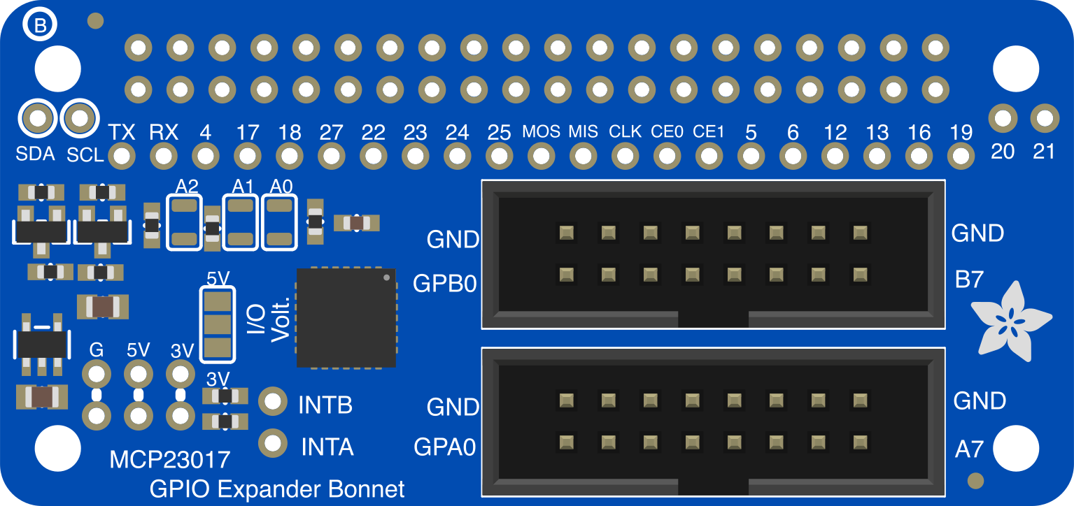
 Design with Adafruit GPIO Expander Bonnet - 16 Additional I/O over I2C in Cirkit Designer
Introduction
The Adafruit GPIO Expander Bonnet (Part ID: 4132) is a compact and versatile board designed to provide 16 additional general-purpose input/output (GPIO) pins to your microcontroller or single-board computer. It communicates via the I2C interface, making it an excellent choice for projects requiring more GPIO pins than your device natively supports. This bonnet is particularly well-suited for Raspberry Pi and other I2C-compatible platforms.
Explore Projects Built with Adafruit GPIO Expander Bonnet - 16 Additional I/O over I2C
 Open Project in Cirkit Designer
 Open Project in Cirkit Designer
 Open Project in Cirkit Designer
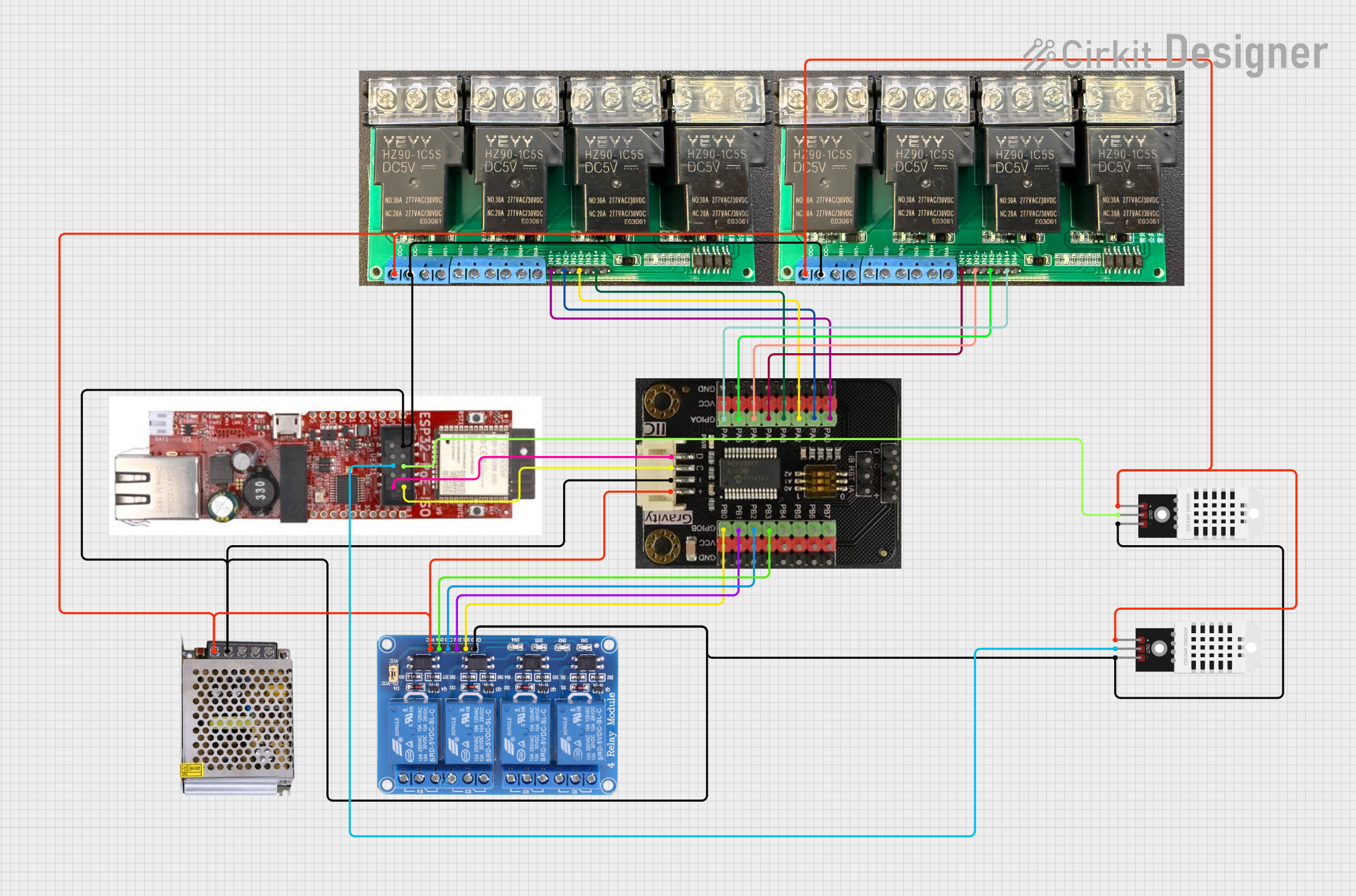 Open Project in Cirkit Designer
Explore Projects Built with Adafruit GPIO Expander Bonnet - 16 Additional I/O over I2C
Open Project in Cirkit DesignerOpen Project in Cirkit DesignerOpen Project in Cirkit DesignerOpen Project in Cirkit DesignerCommon Applications and Use Cases
- Expanding GPIO capabilities for Raspberry Pi or other microcontrollers.
- Controlling LEDs, relays, or other digital devices.
- Reading multiple button inputs or sensors.
- Prototyping and testing circuits requiring additional I/O pins.
Technical Specifications
The Adafruit GPIO Expander Bonnet is based on the MCP23017 I/O expander chip, which provides robust and reliable GPIO expansion over I2C.
Key Technical Details
| Parameter | Value |
|---|---|
| Operating Voltage | 3.3V or 5V |
| Communication Protocol | I2C |
| GPIO Pins | 16 (organized as two 8-bit ports) |
| I2C Address Range | 0x20 to 0x27 (configurable) |
| Maximum Current per Pin | 25mA |
| Pull-up Resistors | Configurable internal pull-ups |
| Dimensions | 65mm x 30mm x 5mm |
Pin Configuration and Descriptions
The GPIO Expander Bonnet has the following key pin connections:
I2C Interface Pins
| Pin Name | Description |
|---|---|
| SDA | I2C Data Line |
| SCL | I2C Clock Line |
| GND | Ground |
| VIN | Power input (3.3V or 5V) |
GPIO Pins
| Pin Name | Description |
|---|---|
| GPA0-GPA7 | General-purpose I/O pins (Port A) |
| GPB0-GPB7 | General-purpose I/O pins (Port B) |
Address Selection Pins
| Pin Name | Description |
|---|---|
| A0, A1, A2 | I2C address configuration pins |
Usage Instructions
How to Use the Component in a Circuit
Connect Power and I2C Lines:
- Connect the
VINpin to a 3.3V or 5V power source. - Connect the
GNDpin to the ground of your microcontroller. - Connect the
SDAandSCLpins to the corresponding I2C pins on your microcontroller.
- Connect the
Configure the I2C Address:
- Use the
A0,A1, andA2pins to set the I2C address. These pins can be tied toGNDorVINto select an address between0x20and0x27.
- Use the
Connect GPIO Devices:
- Attach your input or output devices (e.g., LEDs, buttons, sensors) to the GPIO pins (
GPA0-GPA7andGPB0-GPB7).
- Attach your input or output devices (e.g., LEDs, buttons, sensors) to the GPIO pins (
Install Required Libraries:
- For Raspberry Pi or Arduino, install the Adafruit MCP23017 library to simplify communication with the GPIO expander.
Write Code to Control the GPIO Pins:
- Use the library functions to configure pins as inputs or outputs and to read/write data.
Important Considerations and Best Practices
- Ensure the I2C pull-up resistors are enabled on your microcontroller or add external pull-ups if necessary.
- Avoid exceeding the maximum current rating of 25mA per GPIO pin.
- Use appropriate resistors when connecting LEDs or other components to prevent damage.
- If using multiple MCP23017 devices, ensure each has a unique I2C address.
Example Code for Arduino UNO
Below is an example of how to use the GPIO Expander Bonnet with an Arduino UNO:
#include <Wire.h>
#include "Adafruit_MCP23X17.h"

// Create an MCP23017 object
Adafruit_MCP23X17 mcp;

void setup() {
  Serial.begin(9600); // Initialize serial communication for debugging
  while (!Serial) {
    delay(10); // Wait for Serial Monitor to open
  }

  // Initialize the MCP23017
  if (!mcp.begin_I2C()) {
    Serial.println("Failed to initialize MCP23017. Check connections!");
    while (1);
  }
  Serial.println("MCP23017 initialized successfully!");

  // Set pin GPA0 as an output
  mcp.pinMode(0, OUTPUT);

  // Set pin GPA1 as an input with pull-up resistor enabled
  mcp.pinMode(1, INPUT);
  mcp.pullUp(1, HIGH);
}

void loop() {
  // Blink an LED connected to GPA0
  mcp.digitalWrite(0, HIGH); // Turn LED on
  delay(500);                // Wait 500ms
  mcp.digitalWrite(0, LOW);  // Turn LED off
  delay(500);                // Wait 500ms

  // Read the state of a button connected to GPA1
  if (mcp.digitalRead(1) == LOW) {
    Serial.println("Button pressed!");
  } else {
    Serial.println("Button not pressed.");
  }
  delay(100); // Short delay for stability
}
Troubleshooting and FAQs
Common Issues and Solutions
MCP23017 Not Detected on I2C Bus:
- Ensure the
SDAandSCLlines are correctly connected. - Verify that the I2C address matches the configuration of the
A0,A1, andA2pins. - Check for proper pull-up resistors on the I2C lines.
- Ensure the
GPIO Pins Not Responding:
- Confirm that the pins are correctly configured as inputs or outputs in your code.
- Check for loose or incorrect wiring to the GPIO pins.
Overheating or Damage:
- Ensure the current through each GPIO pin does not exceed 25mA.
- Use appropriate resistors when connecting LEDs or other components.
FAQs
Q: Can I use this bonnet with a 5V microcontroller?
A: Yes, the GPIO Expander Bonnet supports both 3.3V and 5V logic levels.
Q: How many MCP23017 devices can I connect to a single I2C bus?
A: You can connect up to 8 MCP23017 devices by configuring unique I2C addresses using the A0, A1, and A2 pins.
Q: Does the bonnet support PWM output?
A: The MCP23017 does not natively support PWM. However, you can implement software PWM using your microcontroller.
Q: Can I use this with a Raspberry Pi?
A: Yes, the GPIO Expander Bonnet is fully compatible with Raspberry Pi. Use the Adafruit CircuitPython library for easy integration.
This documentation provides all the essential details to get started with the Adafruit GPIO Expander Bonnet. For further assistance, refer to the official Adafruit guide or community forums.