Cirkit Designer Logo
Cirkit Designer
Your all-in-one circuit design IDE
Home / 
Component Documentation

How to Use SW1801P: Examples, Pinouts, and Specs
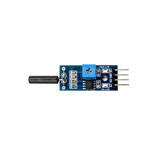
Image of SW1801P
Cirkit Designer LogoDesign with SW1801P in Cirkit Designer

Introduction

The SW1801P is a miniature push-button switch designed for low-power applications. Its compact design makes it ideal for use in tight spaces, such as consumer electronics, control panels, and handheld devices. This switch is commonly used for user input, mode selection, or as a reset button in various electronic circuits. Its reliability and small form factor make it a popular choice for modern electronic designs.

Explore Projects Built with SW1801P
Use Cirkit Designer to design, explore, and prototype these projects online. Some projects support real-time simulation. Click "Open Project" to start designing instantly!
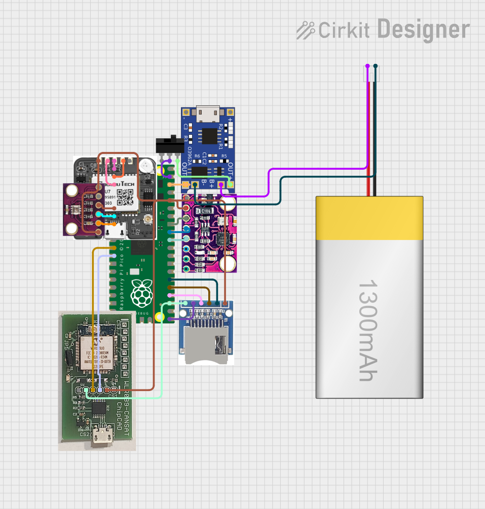
Battery-Powered Raspberry Pi Pico GPS Tracker with Sensor Integration
Image of Copy of CanSet v1: A project utilizing SW1801P in a practical application
This circuit is a data acquisition and communication system powered by a LiPoly battery and managed by a Raspberry Pi Pico. It includes sensors (BMP280, MPU9250) for environmental data, a GPS module for location tracking, an SD card for data storage, and a WLR089-CanSAT for wireless communication. The TP4056 module handles battery charging, and a toggle switch controls power distribution.
Cirkit Designer LogoOpen Project in Cirkit Designer
Satellite Compass and Network-Integrated GPS Data Processing System
Image of GPS 시스템 측정 구성도_241016: A project utilizing SW1801P in a practical application
This circuit comprises a satellite compass, a mini PC, two GPS antennas, power supplies, a network switch, media converters, and an atomic rubidium clock. The satellite compass is powered by a triple output DC power supply and interfaces with an RS232 splitter for 1PPS signals. The mini PCs are connected to the USRP B200 devices via USB for data and power, and to media converters via Ethernet, which in turn connect to a network switch using fiber optic links. The antennas are connected to the USRP B200s through RF directional couplers, and the atomic clock provides a 1PPS input to the RS232 splitter.
Cirkit Designer LogoOpen Project in Cirkit Designer
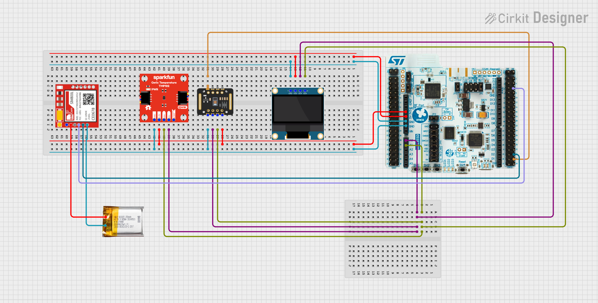
Battery-Powered Health Monitoring System with Nucleo WB55RG and OLED Display
Image of Pulsefex: A project utilizing SW1801P in a practical application
This circuit is a multi-sensor data acquisition system that uses a Nucleo WB55RG microcontroller to interface with a digital temperature sensor (TMP102), a pulse oximeter and heart-rate sensor (MAX30102), and a 0.96" OLED display via I2C. Additionally, it includes a Sim800l module for GSM communication, powered by a 3.7V LiPo battery.
Cirkit Designer LogoOpen Project in Cirkit Designer
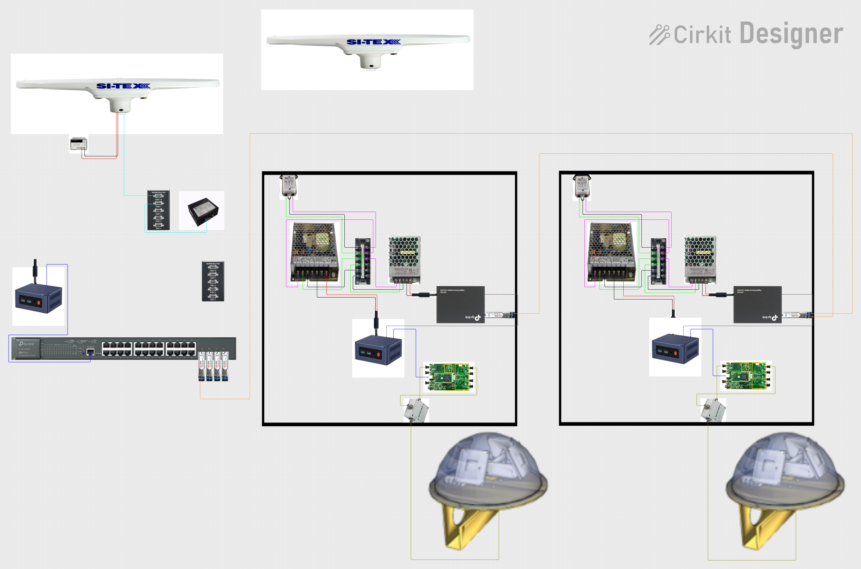
Satellite-Based Timing and Navigation System with SDR and Atomic Clock Synchronization
Image of GPS 시스템 측정 구성도_Confirm: A project utilizing SW1801P in a practical application
This circuit appears to be a complex system involving power supply management, GPS and timing synchronization, and data communication. It includes a SI-TEX G1 Satellite Compass for GPS data, an XHTF1021 Atomic Rubidium Clock for precise timing, and Ettus USRP B200 units for software-defined radio communication. Power is supplied through various SMPS units and distributed via terminal blocks and DC jacks. Data communication is facilitated by Beelink MINI S12 N95 computers, RS232 splitters, and a 1000BASE-T Media Converter for network connectivity. RF Directional Couplers are used to interface antennas with the USRP units, and the entire system is likely contained within cases for protection and organization.
Cirkit Designer LogoOpen Project in Cirkit Designer

Explore Projects Built with SW1801P

Use Cirkit Designer to design, explore, and prototype these projects online. Some projects support real-time simulation. Click "Open Project" to start designing instantly!
Image of Copy of CanSet v1: A project utilizing SW1801P in a practical application
Battery-Powered Raspberry Pi Pico GPS Tracker with Sensor Integration
This circuit is a data acquisition and communication system powered by a LiPoly battery and managed by a Raspberry Pi Pico. It includes sensors (BMP280, MPU9250) for environmental data, a GPS module for location tracking, an SD card for data storage, and a WLR089-CanSAT for wireless communication. The TP4056 module handles battery charging, and a toggle switch controls power distribution.
Cirkit Designer LogoOpen Project in Cirkit Designer
Image of GPS 시스템 측정 구성도_241016: A project utilizing SW1801P in a practical application
Satellite Compass and Network-Integrated GPS Data Processing System
This circuit comprises a satellite compass, a mini PC, two GPS antennas, power supplies, a network switch, media converters, and an atomic rubidium clock. The satellite compass is powered by a triple output DC power supply and interfaces with an RS232 splitter for 1PPS signals. The mini PCs are connected to the USRP B200 devices via USB for data and power, and to media converters via Ethernet, which in turn connect to a network switch using fiber optic links. The antennas are connected to the USRP B200s through RF directional couplers, and the atomic clock provides a 1PPS input to the RS232 splitter.
Cirkit Designer LogoOpen Project in Cirkit Designer
Image of Pulsefex: A project utilizing SW1801P in a practical application
Battery-Powered Health Monitoring System with Nucleo WB55RG and OLED Display
This circuit is a multi-sensor data acquisition system that uses a Nucleo WB55RG microcontroller to interface with a digital temperature sensor (TMP102), a pulse oximeter and heart-rate sensor (MAX30102), and a 0.96" OLED display via I2C. Additionally, it includes a Sim800l module for GSM communication, powered by a 3.7V LiPo battery.
Cirkit Designer LogoOpen Project in Cirkit Designer
Image of GPS 시스템 측정 구성도_Confirm: A project utilizing SW1801P in a practical application
Satellite-Based Timing and Navigation System with SDR and Atomic Clock Synchronization
This circuit appears to be a complex system involving power supply management, GPS and timing synchronization, and data communication. It includes a SI-TEX G1 Satellite Compass for GPS data, an XHTF1021 Atomic Rubidium Clock for precise timing, and Ettus USRP B200 units for software-defined radio communication. Power is supplied through various SMPS units and distributed via terminal blocks and DC jacks. Data communication is facilitated by Beelink MINI S12 N95 computers, RS232 splitters, and a 1000BASE-T Media Converter for network connectivity. RF Directional Couplers are used to interface antennas with the USRP units, and the entire system is likely contained within cases for protection and organization.
Cirkit Designer LogoOpen Project in Cirkit Designer

Technical Specifications

The SW1801P is a momentary push-button switch, meaning it only maintains its state while being pressed. Below are the key technical details and pin configuration:

Key Technical Details

Parameter Value
Operating Voltage 12V DC (maximum)
Operating Current 50mA (maximum)
Contact Resistance ≤ 100mΩ
Insulation Resistance ≥ 100MΩ at 500V DC
Dielectric Strength 250V AC for 1 minute
Operating Temperature -25°C to +85°C
Mechanical Durability 100,000 cycles (minimum)
Switch Type Momentary (Normally Open)

Pin Configuration and Descriptions

The SW1801P typically has two pins, as shown in the table below:

Pin Number Description
1 Switch Terminal 1 (connect to circuit)
2 Switch Terminal 2 (connect to circuit)

When the button is pressed, the two terminals are electrically connected, allowing current to flow through the switch.

Usage Instructions

How to Use the SW1801P in a Circuit

  1. Basic Connection:

    • Connect one terminal of the SW1801P to the positive voltage source (e.g., 5V or 3.3V).
    • Connect the other terminal to the input pin of your microcontroller or circuit, with a pull-down resistor (typically 10kΩ) to ground. This ensures the input pin reads a low state when the button is not pressed.
  2. Debouncing:

    • Mechanical switches like the SW1801P can produce noise or "bouncing" when pressed or released. Use a capacitor (e.g., 0.1µF) across the switch terminals or implement software debouncing in your microcontroller to ensure stable operation.
  3. Example Circuit:
    Below is a simple circuit diagram for connecting the SW1801P to an Arduino UNO:

    • Terminal 1 → 5V (Arduino)
    • Terminal 2 → Digital Pin 2 (Arduino) with a 10kΩ pull-down resistor to GND.

Arduino Code Example

The following code demonstrates how to use the SW1801P with an Arduino UNO to toggle an LED when the button is pressed:

// Define pin numbers
const int buttonPin = 2;  // SW1801P connected to digital pin 2
const int ledPin = 13;    // Built-in LED on pin 13

// Variable to store button state
int buttonState = 0;

void setup() {
  pinMode(buttonPin, INPUT);  // Set button pin as input
  pinMode(ledPin, OUTPUT);   // Set LED pin as output
}

void loop() {
  // Read the state of the button
  buttonState = digitalRead(buttonPin);

  // If the button is pressed, turn on the LED
  if (buttonState == HIGH) {
    digitalWrite(ledPin, HIGH);  // Turn on LED
  } else {
    digitalWrite(ledPin, LOW);   // Turn off LED
  }
}

Important Considerations and Best Practices

  • Voltage and Current Ratings: Ensure the operating voltage and current do not exceed the specified limits (12V DC and 50mA). Exceeding these limits may damage the switch.
  • Debouncing: Always account for switch bounce in your design to avoid erratic behavior.
  • Mounting: Handle the switch carefully during soldering to avoid overheating, which could damage the internal mechanism.

Troubleshooting and FAQs

Common Issues and Solutions

  1. The switch does not respond when pressed:

    • Verify the connections and ensure the switch terminals are properly soldered.
    • Check if the pull-down resistor is correctly connected to ground.
  2. The circuit behaves erratically when the button is pressed:

    • This is likely due to switch bounce. Add a capacitor across the switch terminals or implement software debouncing in your code.
  3. The switch feels stuck or unresponsive:

    • Inspect the switch for physical damage or debris. Replace the switch if necessary.
  4. The switch gets hot during operation:

    • Ensure the current passing through the switch does not exceed 50mA. Use a current-limiting resistor if needed.

FAQs

Q: Can the SW1801P be used for AC applications?
A: No, the SW1801P is designed for low-power DC applications only. Using it with AC voltage may damage the switch or cause unsafe operation.

Q: How do I extend the lifespan of the switch?
A: Operate the switch within its rated voltage and current limits, and avoid excessive mechanical stress during use.

Q: Can I use the SW1801P without a pull-down resistor?
A: While it is possible, it is not recommended. Without a pull-down resistor, the input pin of your microcontroller may float, leading to unreliable readings.

By following these guidelines, you can effectively integrate the SW1801P into your electronic projects.