How to Use NPN Transistor (ECB): Examples, Pinouts, and Specs

Introduction
An NPN transistor is a fundamental electronic component used in various applications to amplify and switch electronic signals. It is a type of bipolar junction transistor (BJT) that consists of three layers of semiconductor material, with the order being N-type, P-type, and N-type. The ECB (Emitter-Collector-Base) configuration refers to a specific pin arrangement where the Emitter is the first pin, followed by the Collector, and then the Base. This configuration is essential for certain circuit designs where the physical layout of the transistor's terminals is a consideration.
Common applications of NPN transistors include:
- Amplifiers (audio, signal)
- Switching circuits
- Digital logic circuits (e.g., inverters)
- Oscillators
- Voltage regulators
Explore Projects Built with NPN Transistor (ECB)
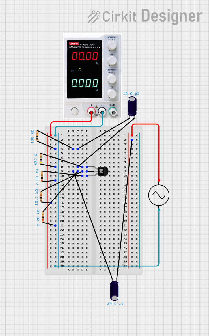

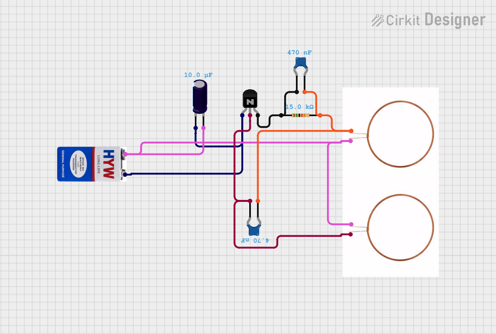
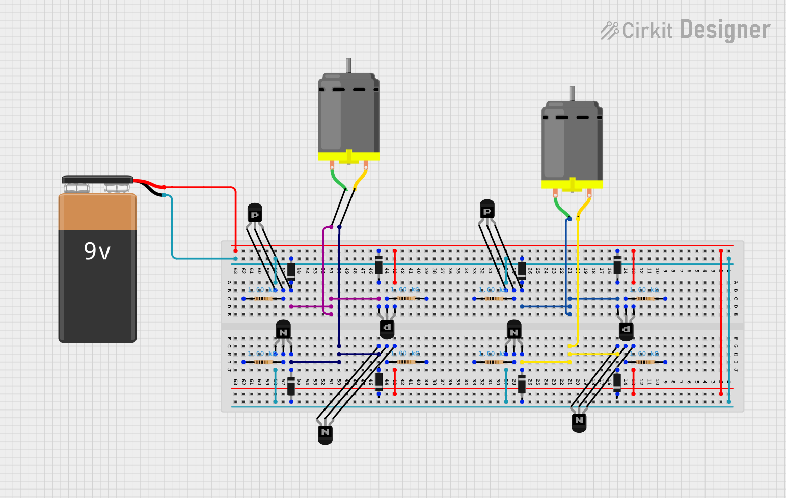
Explore Projects Built with NPN Transistor (ECB)
Technical Specifications
Key Technical Details
- Type: Bipolar Junction Transistor (BJT)
- Polarity: NPN
- Maximum Collector-Emitter Voltage (Vce): Specified by manufacturer (e.g., 40V)
- Maximum Collector Current (Ic): Specified by manufacturer (e.g., 200mA)
- Maximum Base Current (Ib): Specified by manufacturer (e.g., 20mA)
- Power Dissipation: Specified by manufacturer (e.g., 625mW)
Pin Configuration and Descriptions
| Pin Number | Name | Description |
|---|---|---|
| 1 | Emitter | Emits electrons into the base |
| 2 | Collector | Collects electrons from the emitter |
| 3 | Base | Controls the transistor's operation |
Usage Instructions
How to Use the NPN Transistor in a Circuit
Biasing the Transistor: Apply a small current to the base-emitter junction to turn the transistor on. This allows a larger current to flow from the collector to the emitter.
Amplification: To use the transistor as an amplifier, connect it in a common-emitter configuration. The input signal is applied to the base, and the output is taken from the collector.
Switching: For switching applications, the transistor is driven into saturation (fully on) or cutoff (fully off) states.
Important Considerations and Best Practices
- Saturation and Cutoff: Ensure that the base current is sufficient to drive the transistor into saturation when used as a switch.
- Heat Dissipation: Use a heatsink if the power dissipation is expected to be high.
- Resistor Protection: Always use a base resistor to limit the current into the base and prevent damage to the transistor.
- Voltage Ratings: Do not exceed the maximum voltage and current ratings specified by the manufacturer.
Example Circuit: NPN Transistor as a Switch
// Arduino code to use an NPN transistor as a switch to control an LED.

const int ledPin = 13; // LED connected to digital pin 13
const int transistorPin = 2; // Transistor base connected to digital pin 2

void setup() {
  pinMode(ledPin, OUTPUT); // Set the LED pin as output
  pinMode(transistorPin, OUTPUT); // Set the transistor pin as output
}

void loop() {
  digitalWrite(transistorPin, HIGH); // Turn on the transistor
  digitalWrite(ledPin, HIGH); // Turn on the LED
  delay(1000); // Wait for 1 second
  digitalWrite(transistorPin, LOW); // Turn off the transistor
  digitalWrite(ledPin, LOW); // Turn off the LED
  delay(1000); // Wait for 1 second
}
In this example, the Arduino controls the base of the NPN transistor through a digital pin. When the pin is set to HIGH, the transistor allows current to flow from the collector to the emitter, turning on the LED. When the pin is set to LOW, the transistor blocks the current, and the LED turns off.
Troubleshooting and FAQs
Common Issues
- Transistor Not Switching: Check if the base current is sufficient and if the base-emitter voltage is above the threshold.
- Excessive Heat: Ensure the transistor is not operating above its maximum power dissipation.
- Unexpected Behavior: Verify that the transistor is not installed backward and that the pinout matches the ECB configuration.
Solutions and Tips
- Base Resistor Calculation: Use Ohm's law to calculate the appropriate base resistor value to limit the base current.
- Thermal Management: Use a heatsink or improve airflow around the transistor if it is getting too hot.
- Testing Transistor: Use a multimeter to test the transistor's junctions for proper operation.
FAQs
Q: Can I use an NPN transistor to control AC loads? A: NPN transistors are designed for DC applications. To control AC loads, consider using a relay or a TRIAC with an appropriate interface circuit.
Q: How do I choose the right NPN transistor for my project? A: Consider the maximum voltage and current that the transistor will need to handle, as well as the gain (hFE) required for your application.
Q: What happens if I reverse the collector and emitter? A: The transistor will not function correctly as the collector and emitter are doped differently and are not interchangeable.
Remember to always consult the manufacturer's datasheet for the specific NPN transistor model you are using to ensure correct usage and to understand its limitations and specifications.