How to Use 100kg Load Cell Sensor: Examples, Pinouts, and Specs
Introduction
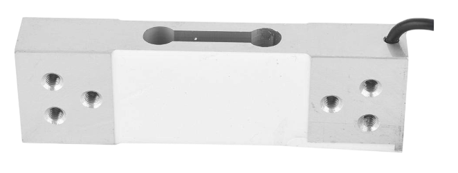
The 100kg Load Cell Sensor is a transducer that converts applied force or weight into an electrical signal. It is specifically designed to measure loads up to 100 kilograms with high accuracy and reliability. This sensor is widely used in applications such as digital weighing scales, industrial automation, force measurement systems, and other weight-sensing devices. Its compact design and robust construction make it suitable for both commercial and industrial environments.
Explore Projects Built with 100kg Load Cell Sensor


Explore Projects Built with 100kg Load Cell Sensor
Technical Specifications
Below are the key technical details of the 100kg Load Cell Sensor:
| Parameter | Specification |
|---|---|
| Rated Load | 100 kg |
| Output Sensitivity | 1.0 ± 0.1 mV/V |
| Excitation Voltage | 5V to 12V DC (recommended: 10V DC) |
| Maximum Excitation | 15V DC |
| Zero Balance | ±0.1 mV/V |
| Input Resistance | 405 ± 10 ohms |
| Output Resistance | 350 ± 3 ohms |
| Safe Overload | 120% of rated load |
| Ultimate Overload | 150% of rated load |
| Operating Temperature | -10°C to +40°C |
| Material | Aluminum Alloy |
| Cable Length | 1 meter |
Pin Configuration and Descriptions
The 100kg Load Cell Sensor typically comes with a 4-wire configuration. The table below describes the wire connections:
| Wire Color | Function | Description |
|---|---|---|
| Red | Excitation+ (E+) | Positive power supply for the sensor |
| Black | Excitation- (E-) | Negative power supply for the sensor |
| White | Signal+ (S+) | Positive output signal |
| Green | Signal- (S-) | Negative output signal |
Usage Instructions
How to Use the 100kg Load Cell Sensor in a Circuit
Wiring the Load Cell:
- Connect the red wire (E+) to the positive terminal of the excitation voltage (e.g., 5V or 10V DC).
- Connect the black wire (E-) to the ground (GND) of the power supply.
- Connect the white wire (S+) to the positive input of an amplifier or ADC (Analog-to-Digital Converter).
- Connect the green wire (S-) to the negative input of the amplifier or ADC.
Amplification and Signal Processing:
- The output signal of the load cell is in millivolts (mV) and requires amplification.
- Use a load cell amplifier module, such as the HX711, to amplify the signal and convert it to a digital format.
Connecting to a Microcontroller:
- The amplified signal can be interfaced with a microcontroller (e.g., Arduino UNO) for further processing.
- The HX711 module simplifies the connection by providing a digital output that can be read by the microcontroller.
Example: Using the Load Cell with Arduino UNO
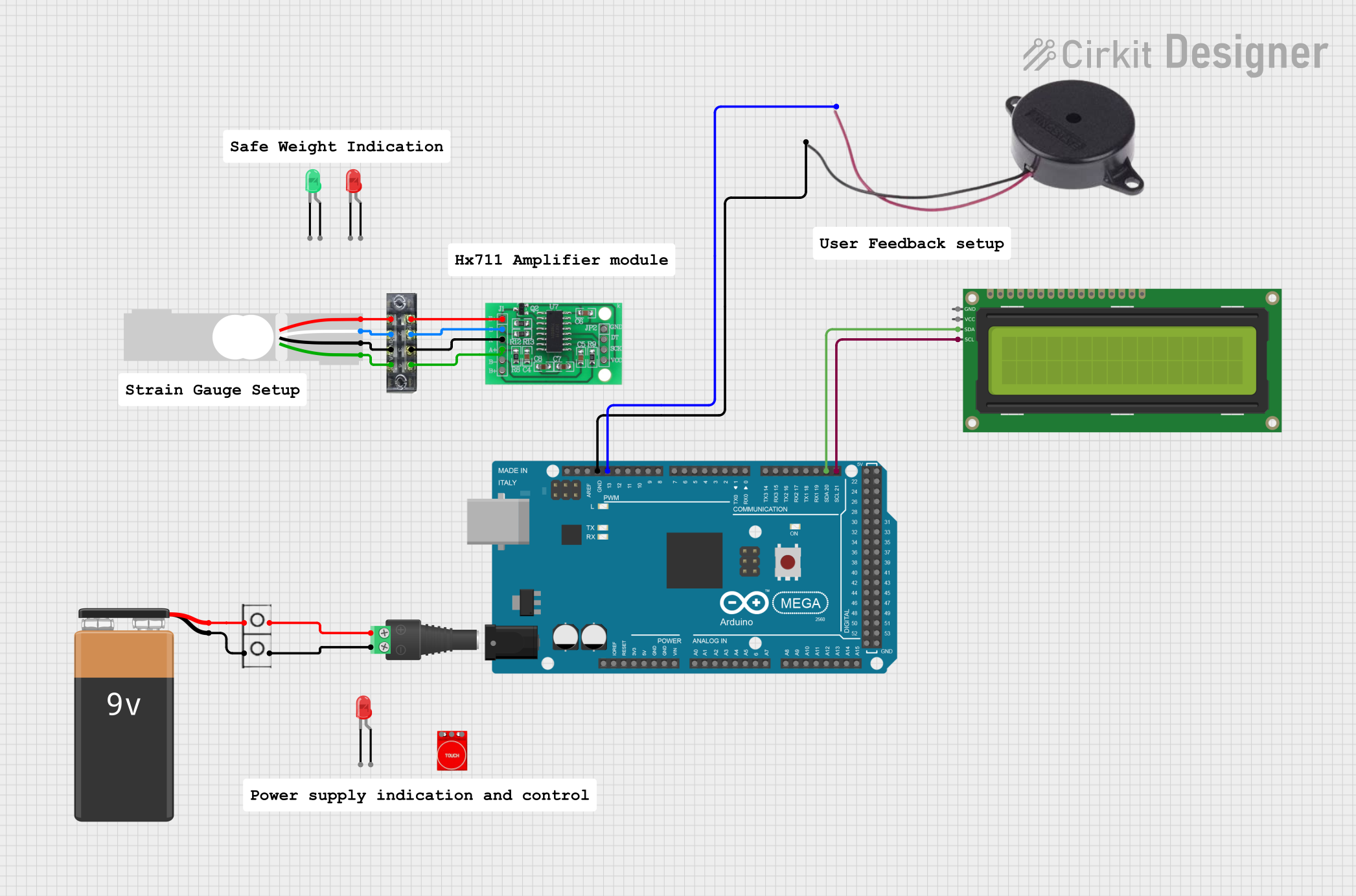
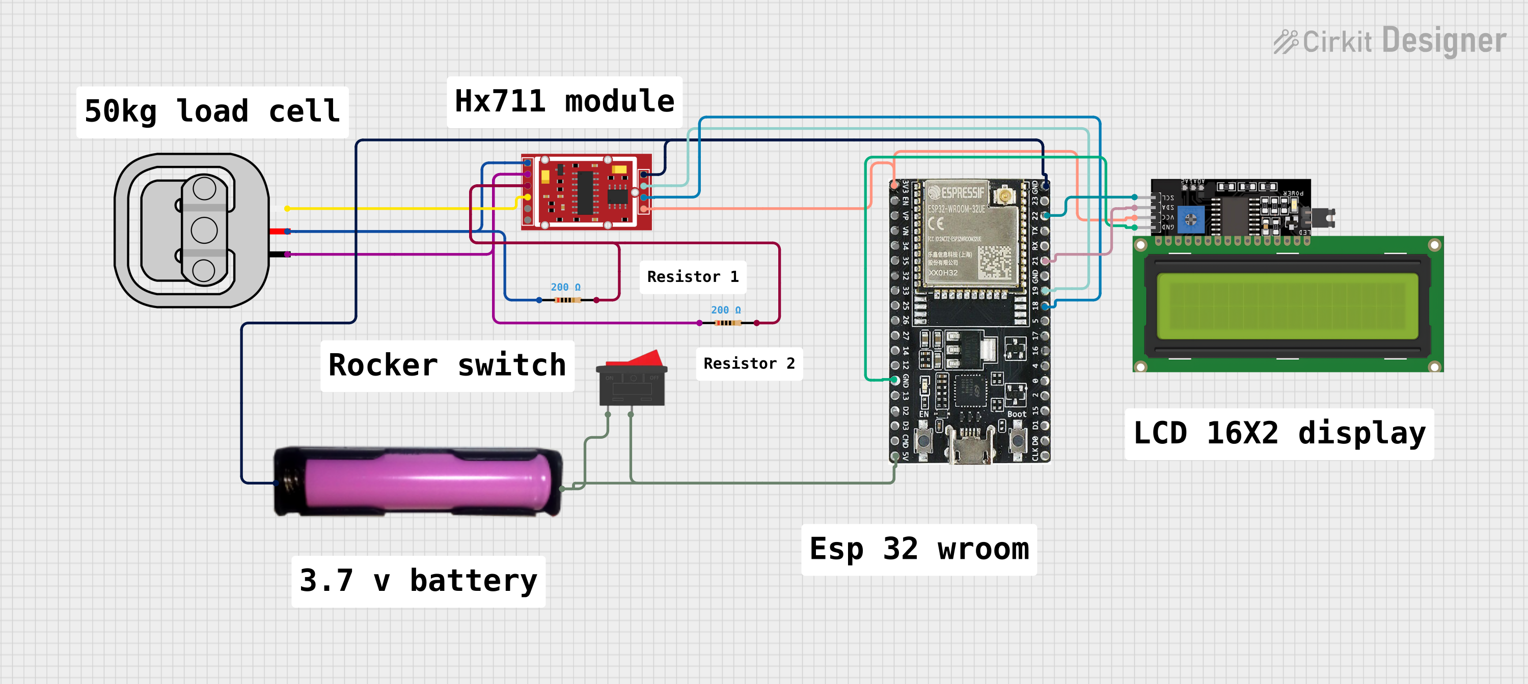
Below is an example of how to connect and use the 100kg Load Cell Sensor with an Arduino UNO and an HX711 module:
Wiring Diagram
- Connect the load cell wires to the HX711 module as follows:
- Red (E+) → E+ on HX711
- Black (E-) → E- on HX711
- White (S+) → A+ on HX711
- Green (S-) → A- on HX711
- Connect the HX711 module to the Arduino UNO:
- VCC → 5V on Arduino
- GND → GND on Arduino
- DT → Digital Pin 3 on Arduino
- SCK → Digital Pin 2 on Arduino
Arduino Code
#include "HX711.h"

// Define HX711 pins
#define DT 3  // Data pin connected to digital pin 3
#define SCK 2 // Clock pin connected to digital pin 2

HX711 scale;

void setup() {
  Serial.begin(9600); // Initialize serial communication
  scale.begin(DT, SCK); // Initialize HX711 with defined pins

  Serial.println("Initializing scale...");
  scale.set_scale(); // Set the scale factor (calibration required)
  scale.tare();      // Reset the scale to zero
  Serial.println("Scale initialized.");
}

void loop() {
  // Read weight from the load cell
  float weight = scale.get_units(); // Get weight in user-defined units
  Serial.print("Weight: ");
  Serial.print(weight);
  Serial.println(" kg");

  delay(500); // Delay for readability
}
Important Considerations and Best Practices
- Calibration: The load cell must be calibrated to ensure accurate weight measurements. Use known weights to determine the scale factor.
- Overload Protection: Avoid exceeding the rated load (100kg) to prevent damage to the sensor.
- Stable Power Supply: Use a stable and noise-free power supply to minimize signal fluctuations.
- Mounting: Ensure the load cell is securely mounted and the load is applied evenly to avoid measurement errors.
Troubleshooting and FAQs
Common Issues and Solutions
No Output Signal:
- Check all wire connections for proper contact.
- Ensure the excitation voltage is within the specified range (5V to 12V DC).
Inaccurate Measurements:
- Verify that the load cell is properly calibrated.
- Check for mechanical interference or uneven load distribution.
Fluctuating Readings:
- Use a stable power supply to reduce noise.
- Ensure the load cell is not exposed to vibrations or environmental disturbances.
No Response from HX711:
- Confirm that the HX711 module is correctly connected to the Arduino.
- Check the Arduino code for correct pin assignments.
FAQs
Q: Can I use the 100kg Load Cell Sensor with a Raspberry Pi?
A: Yes, the load cell can be used with a Raspberry Pi by interfacing it through an HX711 module. Use GPIO pins to read the digital output from the HX711.
Q: How do I calibrate the load cell?
A: Calibration involves determining the scale factor by using a known weight. Adjust the scale factor in your code until the output matches the known weight.
Q: What happens if I exceed the rated load?
A: Exceeding the rated load (100kg) may permanently damage the load cell. Avoid applying loads beyond the safe overload limit (120% of the rated load).
Q: Can I use multiple load cells in a single system?
A: Yes, multiple load cells can be used in parallel to measure larger weights or distributed loads. Ensure proper wiring and signal processing for accurate results.