Cirkit Designer
Your all-in-one circuit design IDE
Home /
Component Documentation
How to Use ESP8266-05: Examples, Pinouts, and Specs
Introduction
The ESP8266-05 is a low-cost Wi-Fi microchip with a full TCP/IP stack and microcontroller capability. It is widely used in Internet of Things (IoT) applications due to its affordability, ease of use, and robust feature set. This component allows devices to connect to Wi-Fi networks, enabling remote control and data acquisition.
Explore Projects Built with ESP8266-05
ESP8266 NodeMCU Controlled Smart Relay with IR and Temperature Sensing
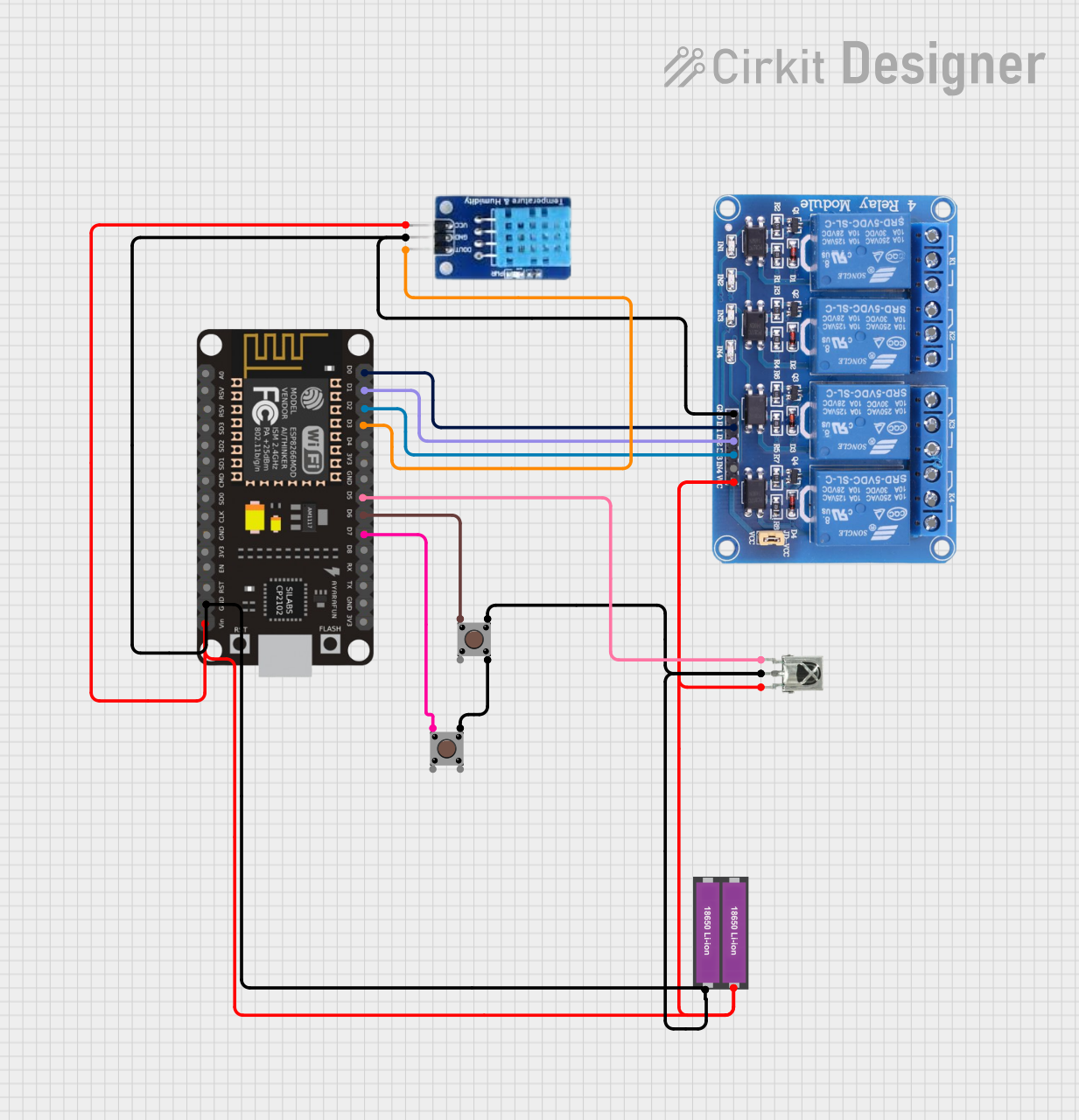
This circuit features an ESP8266 NodeMCU microcontroller connected to a 4-channel relay module, a DHT11 temperature and humidity sensor, a VS1838B infrared receiver, and two pushbuttons. The ESP8266 controls the relay channels via its digital pins D0, D1, and D2, reads temperature and humidity data from the DHT11 sensor connected to pin D3, receives IR signals through the VS1838B connected to pin D5, and monitors the state of the pushbuttons connected to pins D6 and D7. The entire circuit is powered by a series connection of two 18650 Li-ion batteries, with common ground and power distribution to all components.
ESP8266 NodeMCU Based Solar-Powered Relay Control System
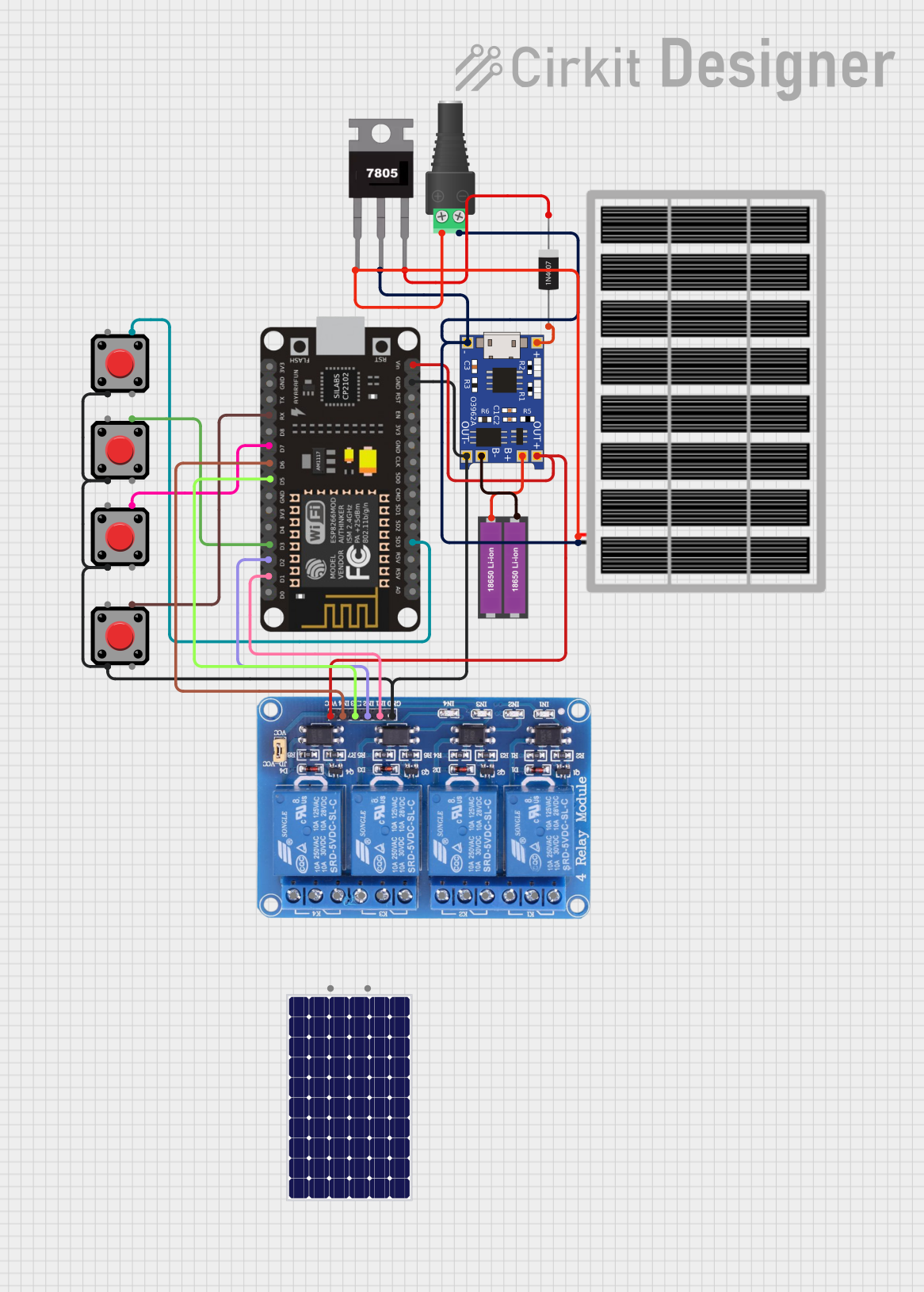
This circuit features an ESP8266 NodeMCU microcontroller interfaced with a 4-channel relay module, allowing for control of external devices. The ESP8266's GPIO pins are connected to the relay inputs and pushbuttons for user interaction. Power management is handled by a TP4056 charging module connected to a pair of 18650 Li-ion batteries, with input from a solar panel through a 1N4007 diode for protection and a 7805 voltage regulator ensuring stable 5V supply to the system.
Wi-Fi Enabled Soil Moisture Monitoring and Water Pump Control System

This circuit features an ESP8266 NodeMCU microcontroller connected to various peripherals. An LCD Display is interfaced via I2C for user interaction, while a DHT11 sensor provides temperature and humidity readings. A relay controls a water pump, possibly for an automated watering system, and a pushbutton is included for user input. Soil moisture is monitored with a YL-83 module connected to a YL-69 probe.
ESP8266 NodeMCU-Based Environmental Monitoring System with Wi-Fi Connectivity
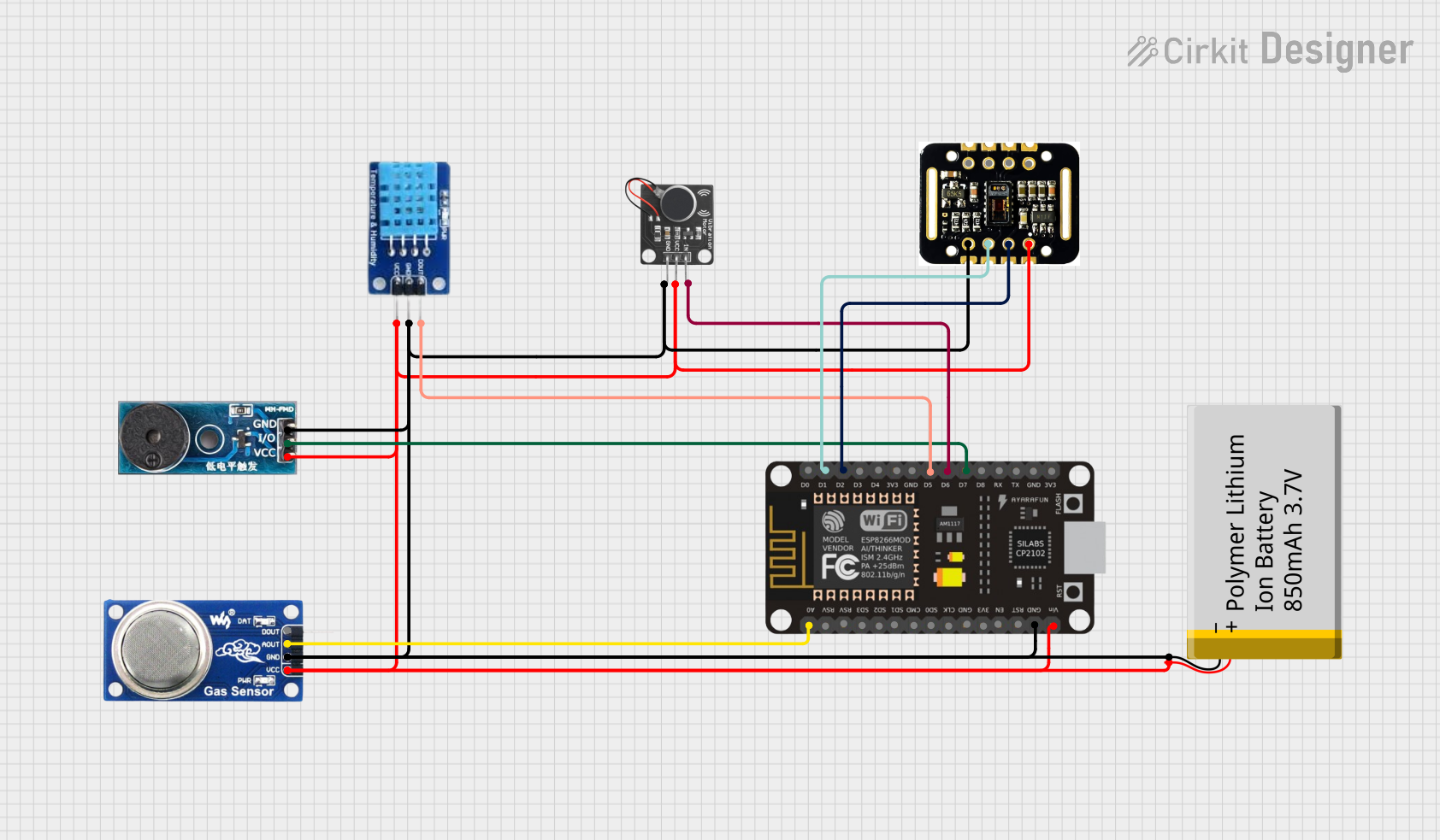
This circuit is designed for environmental monitoring and personal health tracking. It uses an ESP8266 NodeMCU to connect various sensors, including a DHT11 for temperature and humidity, an MQ6 gas sensor for detecting LPG and smoke, a MAX30102 for heart rate and blood oxygen saturation (SpO2) monitoring, and a buzzer and vibration motor for alerts. The system interfaces with the Blynk platform for remote data visualization and can trigger alerts based on sensor readings, such as excessive temperature or gas levels.
Explore Projects Built with ESP8266-05
ESP8266 NodeMCU Controlled Smart Relay with IR and Temperature Sensing
This circuit features an ESP8266 NodeMCU microcontroller connected to a 4-channel relay module, a DHT11 temperature and humidity sensor, a VS1838B infrared receiver, and two pushbuttons. The ESP8266 controls the relay channels via its digital pins D0, D1, and D2, reads temperature and humidity data from the DHT11 sensor connected to pin D3, receives IR signals through the VS1838B connected to pin D5, and monitors the state of the pushbuttons connected to pins D6 and D7. The entire circuit is powered by a series connection of two 18650 Li-ion batteries, with common ground and power distribution to all components.
ESP8266 NodeMCU Based Solar-Powered Relay Control System
This circuit features an ESP8266 NodeMCU microcontroller interfaced with a 4-channel relay module, allowing for control of external devices. The ESP8266's GPIO pins are connected to the relay inputs and pushbuttons for user interaction. Power management is handled by a TP4056 charging module connected to a pair of 18650 Li-ion batteries, with input from a solar panel through a 1N4007 diode for protection and a 7805 voltage regulator ensuring stable 5V supply to the system.
Wi-Fi Enabled Soil Moisture Monitoring and Water Pump Control System
This circuit features an ESP8266 NodeMCU microcontroller connected to various peripherals. An LCD Display is interfaced via I2C for user interaction, while a DHT11 sensor provides temperature and humidity readings. A relay controls a water pump, possibly for an automated watering system, and a pushbutton is included for user input. Soil moisture is monitored with a YL-83 module connected to a YL-69 probe.
ESP8266 NodeMCU-Based Environmental Monitoring System with Wi-Fi Connectivity
This circuit is designed for environmental monitoring and personal health tracking. It uses an ESP8266 NodeMCU to connect various sensors, including a DHT11 for temperature and humidity, an MQ6 gas sensor for detecting LPG and smoke, a MAX30102 for heart rate and blood oxygen saturation (SpO2) monitoring, and a buzzer and vibration motor for alerts. The system interfaces with the Blynk platform for remote data visualization and can trigger alerts based on sensor readings, such as excessive temperature or gas levels.
Common Applications and Use Cases
- Home automation systems
- Smart appliances
- Wireless sensor networks
- Remote data logging
- IoT prototyping and development
Technical Specifications
Key Technical Details
| Parameter | Value |
|---|---|
| Operating Voltage | 3.0V - 3.6V |
| Operating Current | 80mA (average) |
| Power Consumption | 0.9W (max) |
| Wi-Fi Standard | 802.11 b/g/n |
| Frequency Range | 2.4GHz - 2.5GHz (ISM Band) |
| Flash Memory | 1MB |
| GPIO Pins | 2 |
| UART Baud Rate | 9600 - 115200 (default 9600) |
Pin Configuration and Descriptions
| Pin Number | Pin Name | Description |
|---|---|---|
| 1 | VCC | Power supply (3.0V - 3.6V) |
| 2 | GND | Ground |
| 3 | TX | UART Transmit |
| 4 | RX | UART Receive |
| 5 | CH_PD | Chip Power-Down (active high) |
| 6 | RST | Reset (active low) |
Usage Instructions
How to Use the ESP8266-05 in a Circuit
- Power Supply: Connect the VCC pin to a 3.3V power supply and the GND pin to ground.
- UART Communication: Connect the TX pin of the ESP8266-05 to the RX pin of your microcontroller (e.g., Arduino UNO) and the RX pin of the ESP8266-05 to the TX pin of your microcontroller.
- Chip Power-Down: Connect the CH_PD pin to the VCC to enable the chip.
- Reset: Optionally, connect the RST pin to a digital I/O pin of your microcontroller for resetting the module programmatically.
Important Considerations and Best Practices
- Voltage Levels: Ensure that the ESP8266-05 is powered with a stable 3.3V supply. Using higher voltages can damage the module.
- Decoupling Capacitors: Place a 0.1µF and a 10µF capacitor close to the VCC and GND pins to filter out noise.
- Antenna Placement: For optimal Wi-Fi performance, ensure that the antenna area of the module is free from obstructions and metallic objects.
- Firmware Updates: Keep the firmware updated to the latest version to benefit from bug fixes and new features.
Example Code for Arduino UNO
#include <SoftwareSerial.h>

// Create a SoftwareSerial object to communicate with the ESP8266
SoftwareSerial esp8266(2, 3); // RX, TX

void setup() {
  // Start the hardware serial communication with the computer
  Serial.begin(9600);
  // Start the software serial communication with the ESP8266
  esp8266.begin(9600);

  // Send AT command to check if the module is working
  esp8266.println("AT");
}

void loop() {
  // Check if the ESP8266 has sent any data
  if (esp8266.available()) {
    // Read the data from the ESP8266 and print it to the Serial Monitor
    while (esp8266.available()) {
      char c = esp8266.read();
      Serial.write(c);
    }
  }

  // Check if the user has sent any data from the Serial Monitor
  if (Serial.available()) {
    // Read the data from the Serial Monitor and send it to the ESP8266
    while (Serial.available()) {
      char c = Serial.read();
      esp8266.write(c);
    }
  }
}
Troubleshooting and FAQs
Common Issues and Solutions
ESP8266-05 Not Responding to AT Commands
- Solution: Ensure that the baud rate is correctly set to 9600. Check the wiring connections, especially the TX and RX pins.
Wi-Fi Connection Issues
- Solution: Verify the SSID and password. Ensure that the Wi-Fi network is within range and not overcrowded.
Module Overheating
- Solution: Check the power supply voltage and current. Ensure proper ventilation and avoid placing the module in enclosed spaces.
FAQs
Q1: Can I use the ESP8266-05 with a 5V microcontroller?
- A1: Yes, but you need a level shifter or a voltage divider to step down the 5V signals to 3.3V for the ESP8266-05.
Q2: How do I update the firmware of the ESP8266-05?
- A2: You can use the ESP8266 Flasher tool and a USB-to-serial adapter to upload the latest firmware.
Q3: What is the maximum range of the ESP8266-05?
- A3: The range can vary, but typically it is around 100 meters in open space.
By following this documentation, you should be able to effectively integrate the ESP8266-05 into your projects and troubleshoot common issues. Happy tinkering!