How to Use Tilt Switch: Examples, Pinouts, and Specs
Introduction
A tilt switch is a type of sensor designed to detect the orientation or angle of an object. It operates by using a conductive element, such as a ball or mercury, inside a sealed container. When the switch is tilted beyond a specific angle, the conductive element moves, either closing or opening the circuit. This simple yet effective mechanism makes tilt switches ideal for applications requiring motion or position detection.
Explore Projects Built with Tilt Switch
Explore Projects Built with Tilt Switch
Common Applications and Use Cases
- Detecting the tilt or orientation of devices (e.g., toys, appliances, or tools)
- Safety mechanisms in devices to prevent operation at unsafe angles
- Motion detection in alarm systems
- Automotive systems for rollover detection
- Robotics for position sensing
Technical Specifications
Below are the general technical specifications for a tilt switch (Manufacturer Part ID: 999):
| Parameter | Value |
|---|---|
| Operating Voltage | 3.3V to 5V |
| Maximum Current | 20mA |
| Contact Resistance | < 10Ω (when closed) |
| Insulation Resistance | > 10MΩ (when open) |
| Operating Angle | Typically 15° to 45° |
| Response Time | Instantaneous |
| Operating Temperature | -20°C to 70°C |
| Dimensions | Varies by model (e.g., 10mm x 5mm) |
Pin Configuration and Descriptions
The tilt switch typically has two pins, as described below:
| Pin | Description |
|---|---|
| Pin 1 | Connected to the positive voltage (VCC) or input signal |
| Pin 2 | Connected to ground (GND) or output signal |
Usage Instructions
How to Use the Tilt Switch in a Circuit
Basic Connection:
- Connect one pin of the tilt switch to the positive voltage (e.g., 5V).
- Connect the other pin to the input of a microcontroller or a pull-down resistor to ground.
- When the tilt switch is tilted, the circuit will close, and the microcontroller can detect the change in state.
Debouncing:
- Tilt switches may produce noise or multiple signals when transitioning between states. Use a capacitor (e.g., 0.1µF) across the pins or implement software debouncing in your microcontroller to ensure stable readings.
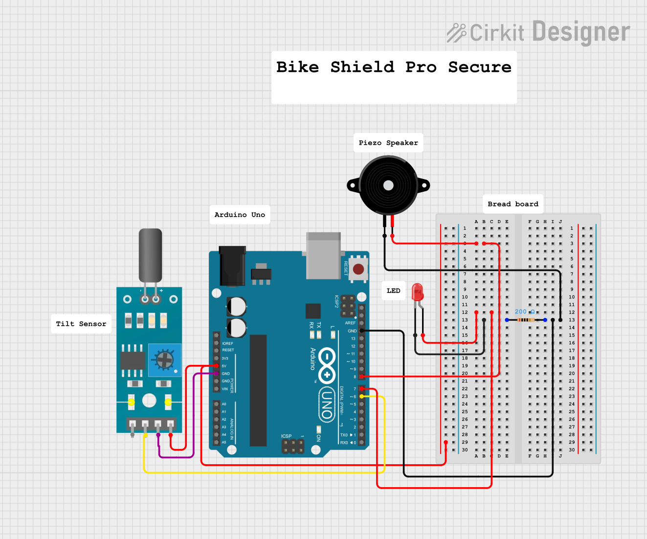
Example Circuit:
- Connect the tilt switch to an Arduino UNO:
- Pin 1 to 5V
- Pin 2 to a digital input pin (e.g., D2) with a pull-down resistor (10kΩ) to ground.
- Connect the tilt switch to an Arduino UNO:
Important Considerations and Best Practices
- Orientation: Ensure the tilt switch is mounted in the correct orientation for your application.
- Environmental Factors: Avoid exposing the switch to extreme temperatures, moisture, or vibrations, as these can affect performance.
- Voltage Levels: Operate the switch within its specified voltage range to prevent damage.
- Debouncing: Always account for signal noise when using the switch in digital circuits.
Arduino Example Code
Below is an example of how to use a tilt switch with an Arduino UNO:
// Tilt Switch Example Code for Arduino UNO
// This code reads the state of a tilt switch and turns on an LED when tilted.

const int tiltSwitchPin = 2; // Pin connected to the tilt switch
const int ledPin = 13;       // Pin connected to the onboard LED

void setup() {
  pinMode(tiltSwitchPin, INPUT); // Set tilt switch pin as input
  pinMode(ledPin, OUTPUT);       // Set LED pin as output
  digitalWrite(ledPin, LOW);     // Ensure LED is off initially
}

void loop() {
  int tiltState = digitalRead(tiltSwitchPin); // Read the tilt switch state

  if (tiltState == HIGH) {
    // If the tilt switch is tilted, turn on the LED
    digitalWrite(ledPin, HIGH);
  } else {
    // If the tilt switch is not tilted, turn off the LED
    digitalWrite(ledPin, LOW);
  }
}
Troubleshooting and FAQs
Common Issues and Solutions
Tilt Switch Not Responding:
- Cause: Incorrect wiring or loose connections.
- Solution: Double-check the wiring and ensure all connections are secure.
Unstable or Noisy Readings:
- Cause: Signal noise or lack of debouncing.
- Solution: Add a capacitor across the pins or implement software debouncing.
Switch Always Reads as Closed or Open:
- Cause: Incorrect orientation or damaged switch.
- Solution: Verify the orientation and replace the switch if necessary.
Microcontroller Not Detecting State Changes:
- Cause: Missing pull-down resistor or incorrect pin configuration.
- Solution: Add a pull-down resistor (e.g., 10kΩ) and ensure the microcontroller pin is set as an input.
FAQs
Q: Can I use a tilt switch with a 3.3V system?
A: Yes, most tilt switches operate within a range of 3.3V to 5V. Check the specific model's datasheet for confirmation.
Q: How do I know the operating angle of my tilt switch?
A: The operating angle is typically specified in the datasheet. For most switches, it ranges between 15° and 45°.
Q: Can I use a tilt switch in high-vibration environments?
A: Tilt switches are not ideal for high-vibration environments, as vibrations can cause false triggering. Consider using a gyroscope or accelerometer for such applications.
Q: Is a mercury-based tilt switch safe to use?
A: Mercury-based tilt switches are less common due to safety and environmental concerns. If using one, handle it carefully and dispose of it properly if damaged.