How to Use IR Speed Grove: Examples, Pinouts, and Specs
Introduction
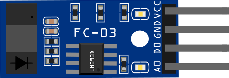
The IR Speed Grove is an infrared sensor module designed to detect the speed of moving objects. It operates by emitting infrared light and measuring the time it takes for the light to reflect off an object and return to the sensor. This module is widely used in applications requiring speed measurement, such as motor speed monitoring, conveyor belt systems, and robotics. Its compact design and ease of integration make it a popular choice for both hobbyists and professionals.
Explore Projects Built with IR Speed Grove

Explore Projects Built with IR Speed Grove
Common Applications
- Motor speed measurement
- Conveyor belt speed monitoring
- Object detection in robotics
- Rotational speed sensing in mechanical systems
- DIY projects involving motion tracking
Technical Specifications
The following table outlines the key technical details of the IR Speed Grove module:
| Parameter | Value |
|---|---|
| Operating Voltage | 3.3V to 5V |
| Operating Current | ≤ 20mA |
| Detection Range | 3mm to 80mm |
| Output Signal | Digital (High/Low) |
| Response Time | ≤ 2ms |
| Operating Temperature | -25°C to 85°C |
| Dimensions | 20mm x 20mm x 10mm |
Pin Configuration
The IR Speed Grove module has a 4-pin interface. The pin descriptions are as follows:
| Pin | Name | Description |
|---|---|---|
| 1 | VCC | Power supply pin (3.3V to 5V) |
| 2 | GND | Ground pin |
| 3 | OUT | Digital output pin (High when object detected) |
| 4 | NC | Not connected (reserved for future use) |
Usage Instructions
How to Use the IR Speed Grove in a Circuit
- Power the Module: Connect the
VCCpin to a 3.3V or 5V power source and theGNDpin to the ground of your circuit. - Connect the Output: Connect the
OUTpin to a digital input pin on your microcontroller or other processing unit. - Position the Sensor: Place the sensor facing the moving object you want to measure. Ensure the object is within the detection range (3mm to 80mm).
- Read the Output: The
OUTpin will output a digital signal:- High (1): When an object is detected.
- Low (0): When no object is detected.
Important Considerations
- Ensure the sensor is not exposed to direct sunlight or strong ambient light, as this may interfere with its performance.
- The detection range may vary depending on the reflectivity of the object. Highly reflective surfaces provide better results.
- Use a pull-down resistor on the
OUTpin if the signal is unstable. - Avoid placing the sensor too close to heat sources, as excessive heat may affect its accuracy.
Example: Connecting to an Arduino UNO
Below is an example of how to use the IR Speed Grove with an Arduino UNO to measure the speed of a rotating object:
Circuit Connections
- Connect the
VCCpin of the IR Speed Grove to the 5V pin on the Arduino. - Connect the
GNDpin of the IR Speed Grove to the GND pin on the Arduino. - Connect the
OUTpin of the IR Speed Grove to digital pin 2 on the Arduino.
Arduino Code
// IR Speed Grove Example Code
// This code reads the digital output from the IR Speed Grove and calculates
// the speed of a rotating object based on the time between pulses.

const int sensorPin = 2; // Pin connected to the OUT pin of the IR Speed Grove
volatile unsigned long lastPulseTime = 0; // Time of the last detected pulse
volatile unsigned long pulseInterval = 0; // Time between two pulses

void setup() {
  pinMode(sensorPin, INPUT); // Set the sensor pin as input
  Serial.begin(9600); // Initialize serial communication
  attachInterrupt(digitalPinToInterrupt(sensorPin), measureSpeed, FALLING);
  // Attach an interrupt to detect falling edges on the sensor pin
}

void loop() {
  if (pulseInterval > 0) {
    // Calculate speed (e.g., in RPM) based on pulse interval
    float speed = 60000.0 / pulseInterval; // Speed in RPM
    Serial.print("Speed: ");
    Serial.print(speed);
    Serial.println(" RPM");
    delay(500); // Update every 500ms
  }
}

void measureSpeed() {
  unsigned long currentTime = millis(); // Get the current time
  pulseInterval = currentTime - lastPulseTime; // Calculate time between pulses
  lastPulseTime = currentTime; // Update the last pulse time
}
Notes on the Code
- The code uses an interrupt to detect changes in the sensor's output, ensuring accurate timing.
- The speed is calculated in revolutions per minute (RPM) based on the time between pulses.
- Adjust the calculation if your application requires a different unit of measurement.
Troubleshooting and FAQs
Common Issues
No Output Signal
- Cause: Incorrect wiring or insufficient power supply.
- Solution: Double-check the connections and ensure the power supply is within the specified range.
Unstable Output
- Cause: Electrical noise or improper grounding.
- Solution: Add a pull-down resistor to the
OUTpin and ensure proper grounding.
Inaccurate Detection
- Cause: Object is outside the detection range or has low reflectivity.
- Solution: Adjust the sensor's position and ensure the object is within the specified range.
Interference from Ambient Light
- Cause: Strong ambient light affecting the sensor's performance.
- Solution: Shield the sensor from direct sunlight or use it in a controlled lighting environment.
FAQs
Can the IR Speed Grove detect transparent objects?
- Transparent objects may not reflect enough infrared light for detection. Use opaque or reflective objects for best results.
What is the maximum speed the sensor can measure?
- The sensor's response time is ≤ 2ms, allowing it to detect speeds up to 500 pulses per second. The actual measurable speed depends on the object's size and distance.
Can I use the IR Speed Grove with a 3.3V microcontroller?
- Yes, the module operates within a voltage range of 3.3V to 5V, making it compatible with 3.3V systems.
How do I clean the sensor?
- Use a soft, dry cloth to clean the sensor lens. Avoid using liquids or abrasive materials.
By following this documentation, you can effectively integrate the IR Speed Grove into your projects and troubleshoot any issues that arise.