How to Use attiny: Examples, Pinouts, and Specs
Introduction
The ATtiny series comprises a family of low-power, single-chip microcontrollers designed and manufactured by Microchip Technology. These microcontrollers are celebrated for their compact size, low power consumption, and high performance. They are based on the AVR enhanced RISC architecture, which enables most instructions to execute in a single clock cycle, enhancing the speed and efficiency of the ATtiny series.
Explore Projects Built with attiny
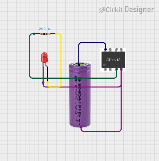
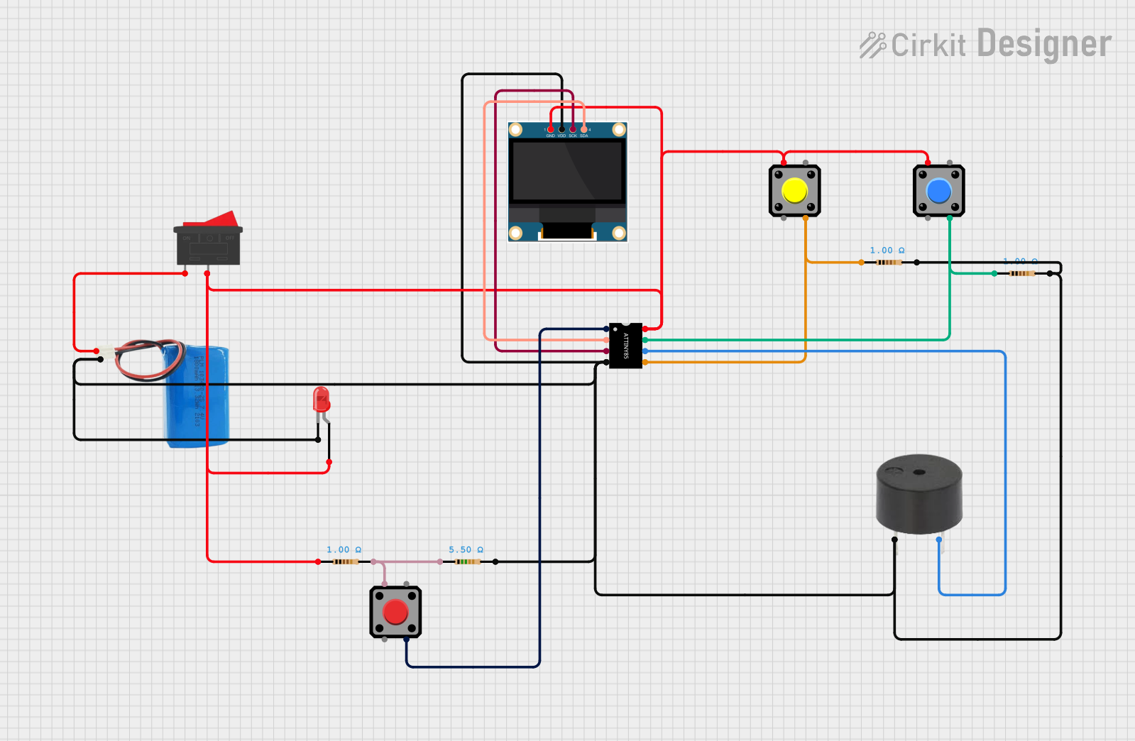


Explore Projects Built with attiny
Common Applications and Use Cases
- Embedded systems
- Consumer electronics
- Wearable devices
- IoT devices
- DIY projects, often interfaced with Arduino boards
- Battery-operated devices
- Sensor nodes
Technical Specifications
The ATtiny series includes several models, each with its own set of specifications. Below is a general overview of the technical specifications for a common ATtiny microcontroller, the ATtiny85.
| Specification | Value |
|---|---|
| CPU | 8-bit AVR |
| Flash Memory | 8 KB |
| SRAM | 512 Bytes |
| EEPROM | 512 Bytes |
| I/O Pins | 6 |
| PWM Channels | 4 |
| ADCs | 4-channel, 10-bit |
| Operating Voltage | 1.8V - 5.5V |
| Clock Speed | Up to 20 MHz |
| Timer Counters | 2 (8-bit), 1 (16-bit) |
| Communication | USI (Universal Serial Interface) |
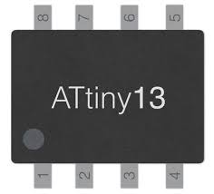
Pin Configuration and Descriptions
| Pin Number | Name | Description |
|---|---|---|
| 1 | PB5 | Reset/ADC0/dW |
| 2 | PB3 | XTAL1/CLKI/ADC3/PCINT3 |
| 3 | PB4 | XTAL2/CLKO/OC1B/ADC2/PCINT4 |
| 4 | GND | Ground |
| 5 | PB0 | MOSI/DI/SDA/AIN0/OC0A/OC1A/AREF/PCINT0 |
| 6 | PB1 | MISO/DO/AIN1/OC0B/OC1A/PCINT1 |
| 7 | PB2 | SCK/USCK/SCL/ADC1/T0/INT0/PCINT2 |
| 8 | VCC | Positive Supply Voltage |
Usage Instructions
Interfacing with a Circuit
- Power Supply: Connect the VCC pin to a power source between 1.8V and 5.5V, and the GND pin to the ground.
- Programming: The ATtiny can be programmed via an ISP (In-System Programmer) or using a bootloader with the Arduino IDE.
- I/O Pins: Configure the I/O pins according to your application needs. They can be used for digital input/output, analog input, PWM output, etc.
Important Considerations and Best Practices
- Ensure that the power supply is within the specified range to prevent damage.
- Use a decoupling capacitor between VCC and GND near the ATtiny to stabilize the power supply.
- When using the ADC, a stable reference voltage is crucial for accurate readings.
- For PWM applications, ensure that the connected devices can handle the frequency and duty cycle.
- Avoid exposing the pins to voltages outside the 0 to VCC range or to high transient spikes.
Troubleshooting and FAQs
Common Issues
- ATtiny not responding: Ensure that the microcontroller is correctly powered and programmed. Check the clock source and reset pin.
- Incorrect behavior in circuit: Verify the pin configuration and ensure that the I/O pins are not overloaded.
- Inaccurate ADC readings: Check the reference voltage and the ADC configuration in your code.
Solutions and Tips
- Always double-check connections before powering up the circuit.
- Use a multimeter to verify voltages and continuity.
- If using an external clock source, ensure it is stable and within the specified frequency range.
FAQs
Q: Can I program the ATtiny with the Arduino IDE? A: Yes, you can program the ATtiny using the Arduino IDE by adding ATtiny support through the board manager.
Q: What is the maximum current that an I/O pin can source or sink? A: An I/O pin can typically source or sink up to 20 mA. However, it's recommended to stay well below this limit for safety.
Q: How do I reset the ATtiny? A: The ATtiny can be reset by momentarily connecting the reset pin (PB5) to ground.
Example Code for Arduino UNO
Below is an example of how to blink an LED connected to pin PB1 of the ATtiny85 using an Arduino UNO as an ISP programmer.
#include <avr/io.h>
#include <util/delay.h>

int main(void) {
    // Set PB1 as an output
    DDRB |= (1 << PB1);

    while (1) {
        // Turn on the LED
        PORTB |= (1 << PB1);
        _delay_ms(1000); // Wait for 1000 milliseconds

        // Turn off the LED
        PORTB &= ~(1 << PB1);
        _delay_ms(1000); // Wait for 1000 milliseconds
    }
}
Remember to configure the Arduino IDE with the appropriate board settings for the ATtiny series before uploading the code. This example assumes you have already set up the ATtiny with a bootloader or are using an ISP to program it.