
How to Use BD3.1 Dyno Controller: Examples, Pinouts, and Specs
 Design with BD3.1 Dyno Controller in Cirkit Designer
Introduction
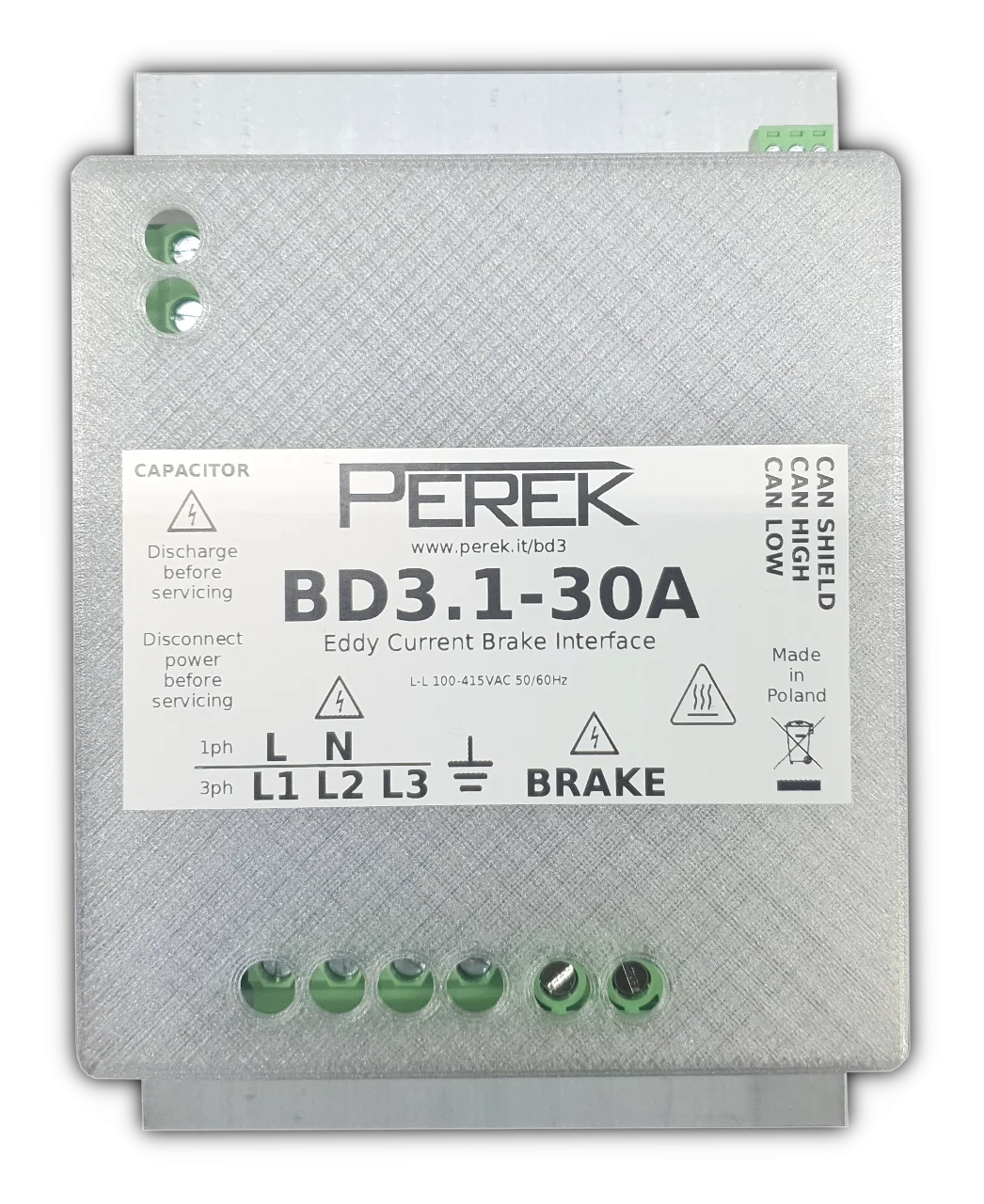
The BD3.1 Dyno Controller by Perek is a sophisticated device designed for managing and monitoring dynamometer testing. It provides precise control over engine performance parameters, enabling accurate data logging and analysis. This controller is ideal for applications requiring high precision in engine testing, such as automotive research, performance tuning, and industrial engine diagnostics.
Explore Projects Built with BD3.1 Dyno Controller
 Open Project in Cirkit Designer
 Open Project in Cirkit Designer
 Open Project in Cirkit Designer
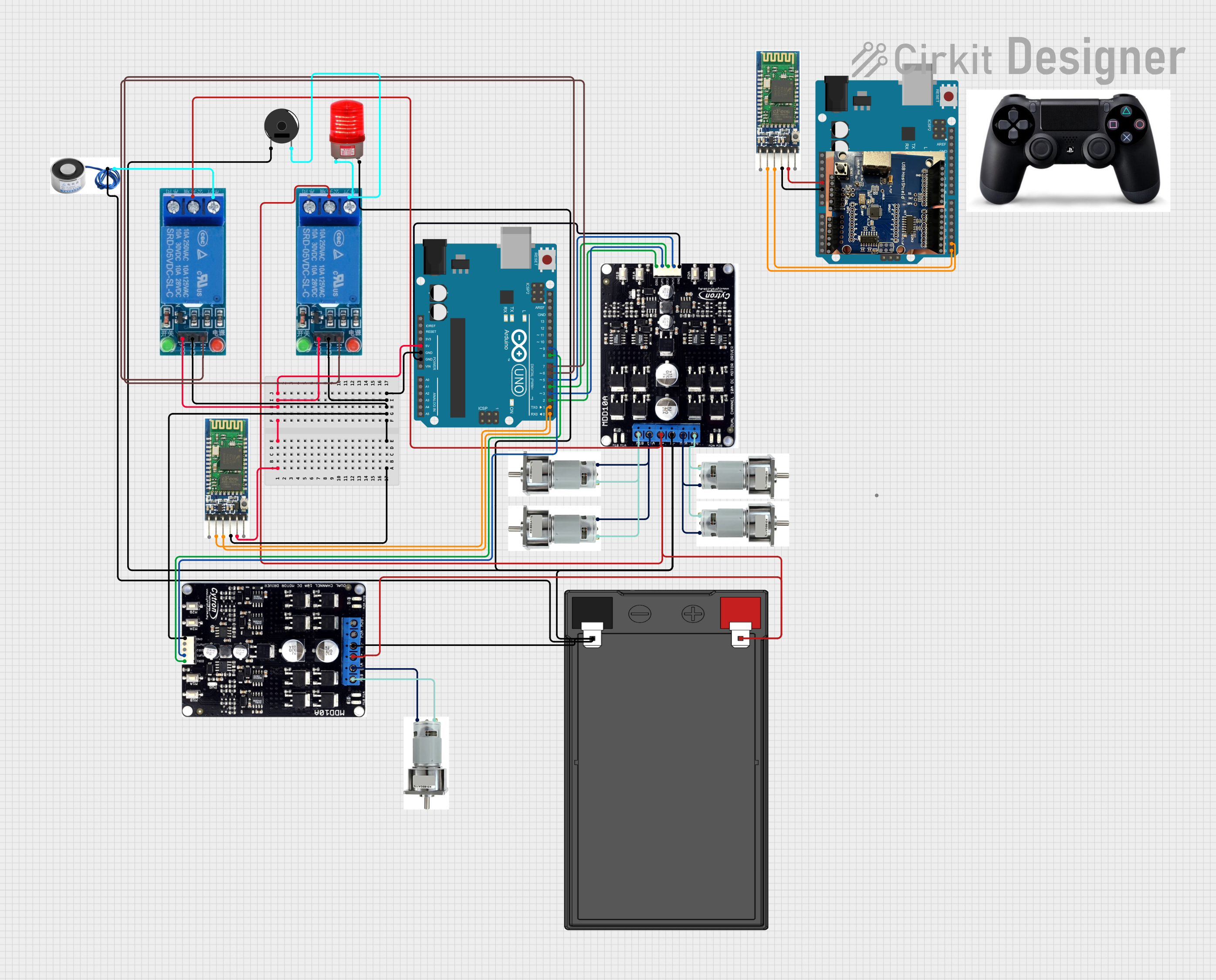 Open Project in Cirkit Designer
Explore Projects Built with BD3.1 Dyno Controller
Open Project in Cirkit DesignerOpen Project in Cirkit DesignerOpen Project in Cirkit DesignerOpen Project in Cirkit DesignerCommon Applications
- Automotive engine performance testing
- Dynamometer-based research and development
- Industrial engine diagnostics and monitoring
- Performance tuning for motorsports
Technical Specifications
Key Technical Details
| Parameter | Specification |
|---|---|
| Manufacturer | Perek |
| Part ID | BD3.1 |
| Input Voltage Range | 12V to 24V DC |
| Maximum Current Draw | 2A |
| Communication Protocols | CAN, UART, USB |
| Data Logging Capability | Up to 32GB (via external storage) |
| Operating Temperature | -20°C to 70°C |
| Control Outputs | PWM, Analog (0-5V), Digital (TTL) |
| Dimensions | 120mm x 80mm x 30mm |
| Weight | 250g |
Pin Configuration and Descriptions
| Pin Number | Pin Name | Description |
|---|---|---|
| 1 | VIN | Power input (12V to 24V DC) |
| 2 | GND | Ground connection |
| 3 | CAN_H | CAN bus high signal |
| 4 | CAN_L | CAN bus low signal |
| 5 | UART_TX | UART transmit signal |
| 6 | UART_RX | UART receive signal |
| 7 | PWM_OUT | PWM output for motor control |
| 8 | ANALOG_OUT | Analog output (0-5V) |
| 9 | DIGITAL_OUT | Digital output (TTL level) |
| 10 | USB | USB interface for data logging and configuration |
Usage Instructions
How to Use the BD3.1 Dyno Controller in a Circuit
- Power Connection: Connect the VIN pin to a 12V-24V DC power source and the GND pin to ground.
- Communication Setup:
- For CAN communication, connect the CAN_H and CAN_L pins to the CAN bus.
- For UART communication, connect the UART_TX and UART_RX pins to the respective UART interface.
- Alternatively, use the USB port for direct communication and configuration.
- Control Outputs:
- Use the PWM_OUT pin to control motor speed or other PWM-compatible devices.
- The ANALOG_OUT pin can be used for analog control signals (e.g., 0-5V).
- The DIGITAL_OUT pin provides a TTL-level digital signal for triggering external devices.
- Data Logging: Insert an external storage device (e.g., USB drive) into the USB port for data logging.
- Configuration: Use the USB interface or UART commands to configure the controller parameters.
Important Considerations and Best Practices
- Ensure the power supply voltage is within the specified range (12V-24V DC) to avoid damage.
- Use proper termination resistors (120Ω) on the CAN bus for reliable communication.
- Shield communication cables to minimize noise interference in high-performance environments.
- Regularly back up logged data from the external storage device to prevent data loss.
- Avoid exposing the controller to temperatures outside the operating range (-20°C to 70°C).
Example: Connecting to an Arduino UNO
The BD3.1 Dyno Controller can be interfaced with an Arduino UNO via UART. Below is an example code snippet for reading data from the controller:
#include <SoftwareSerial.h>

// Define RX and TX pins for SoftwareSerial
SoftwareSerial dynoSerial(10, 11); // RX = Pin 10, TX = Pin 11

void setup() {
  Serial.begin(9600); // Initialize Serial Monitor
  dynoSerial.begin(9600); // Initialize communication with BD3.1

  Serial.println("BD3.1 Dyno Controller Interface Initialized");
}

void loop() {
  // Check if data is available from the BD3.1
  if (dynoSerial.available()) {
    String data = dynoSerial.readStringUntil('\n'); // Read data until newline
    Serial.print("Received Data: ");
    Serial.println(data); // Print received data to Serial Monitor
  }

  // Example: Sending a command to the BD3.1
  if (Serial.available()) {
    String command = Serial.readStringUntil('\n'); // Read command from Serial Monitor
    dynoSerial.println(command); // Send command to BD3.1
    Serial.println("Command Sent to BD3.1");
  }
}
Notes:
- Connect the Arduino's GND to the BD3.1's GND for a common ground.
- Use level shifters if the BD3.1 operates at a different logic level than the Arduino.
Troubleshooting and FAQs
Common Issues and Solutions
No Power to the Controller
- Cause: Incorrect power supply voltage or loose connections.
- Solution: Verify the power supply voltage is within 12V-24V DC and check all connections.
Communication Failure
- Cause: Incorrect wiring or missing termination resistors on the CAN bus.
- Solution: Double-check the wiring and ensure 120Ω termination resistors are installed.
Data Logging Not Working
- Cause: External storage device not recognized.
- Solution: Ensure the storage device is formatted correctly (e.g., FAT32) and securely connected.
PWM Output Not Functioning
- Cause: Incorrect configuration or load connection.
- Solution: Verify the PWM settings and ensure the load is connected properly.
FAQs
Q: Can the BD3.1 Dyno Controller be used with a 5V power supply?
A: No, the BD3.1 requires a power supply within the range of 12V-24V DC.
Q: How do I reset the controller to factory settings?
A: Use the USB interface and the provided configuration software to perform a factory reset.
Q: Is the BD3.1 compatible with other microcontrollers besides Arduino?
A: Yes, the BD3.1 can communicate with any microcontroller that supports UART, CAN, or USB protocols.
Q: Can I use the BD3.1 in outdoor environments?
A: The BD3.1 is not weatherproof. Use it in a protected environment or within an enclosure for outdoor applications.