How to Use Motor Driver 1A Dual TB6612FNG: Examples, Pinouts, and Specs
Introduction
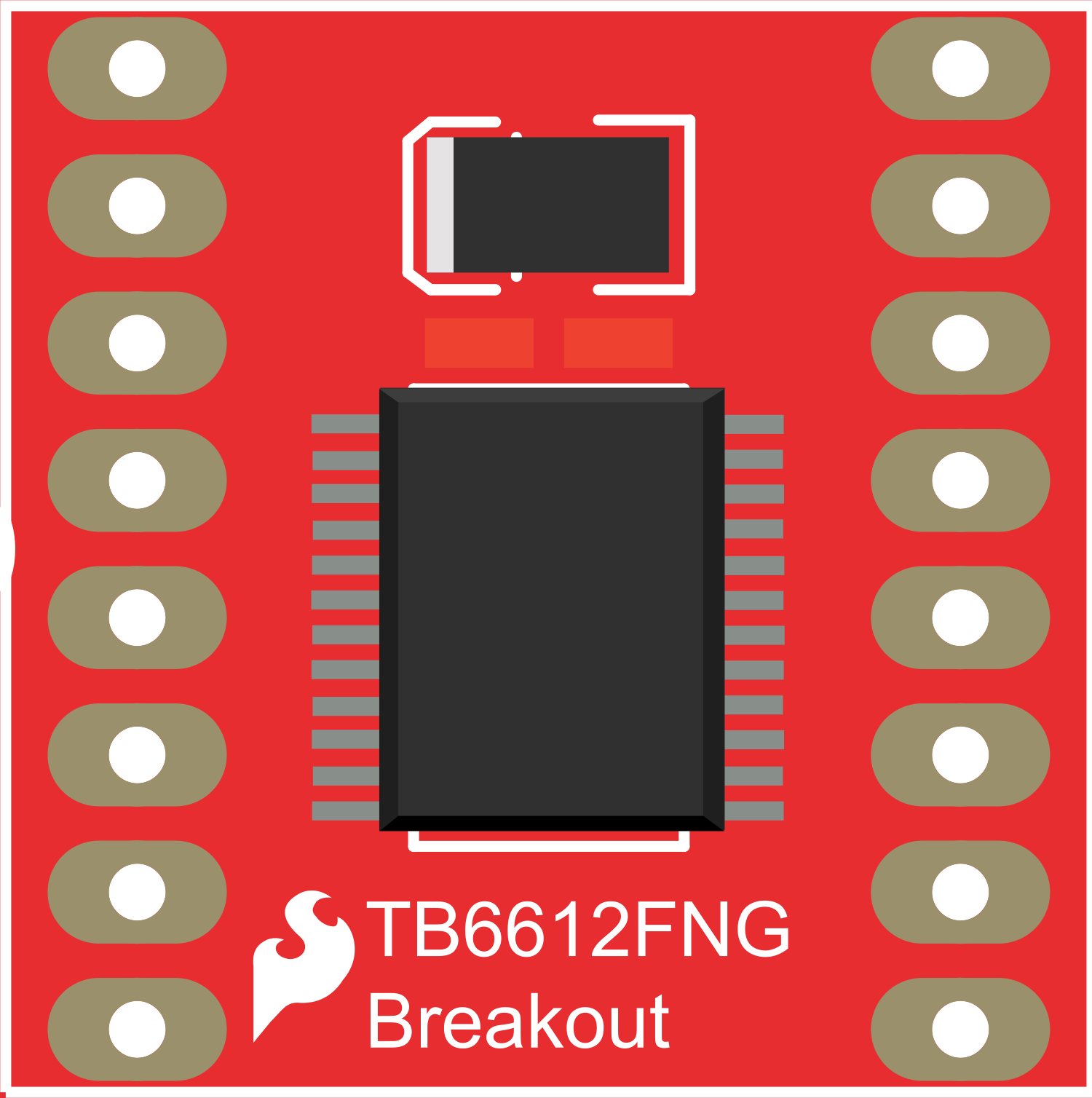
The Motor Driver 1A Dual TB6612FNG is a versatile and efficient motor driver capable of controlling two DC motors or one bipolar stepper motor. Its compact form factor and low power consumption make it ideal for embedded systems, particularly in robotics, automation, and small-scale motor control applications.
Explore Projects Built with Motor Driver 1A Dual TB6612FNG

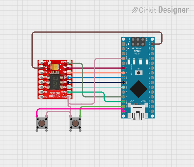
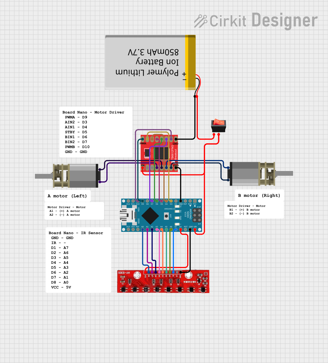
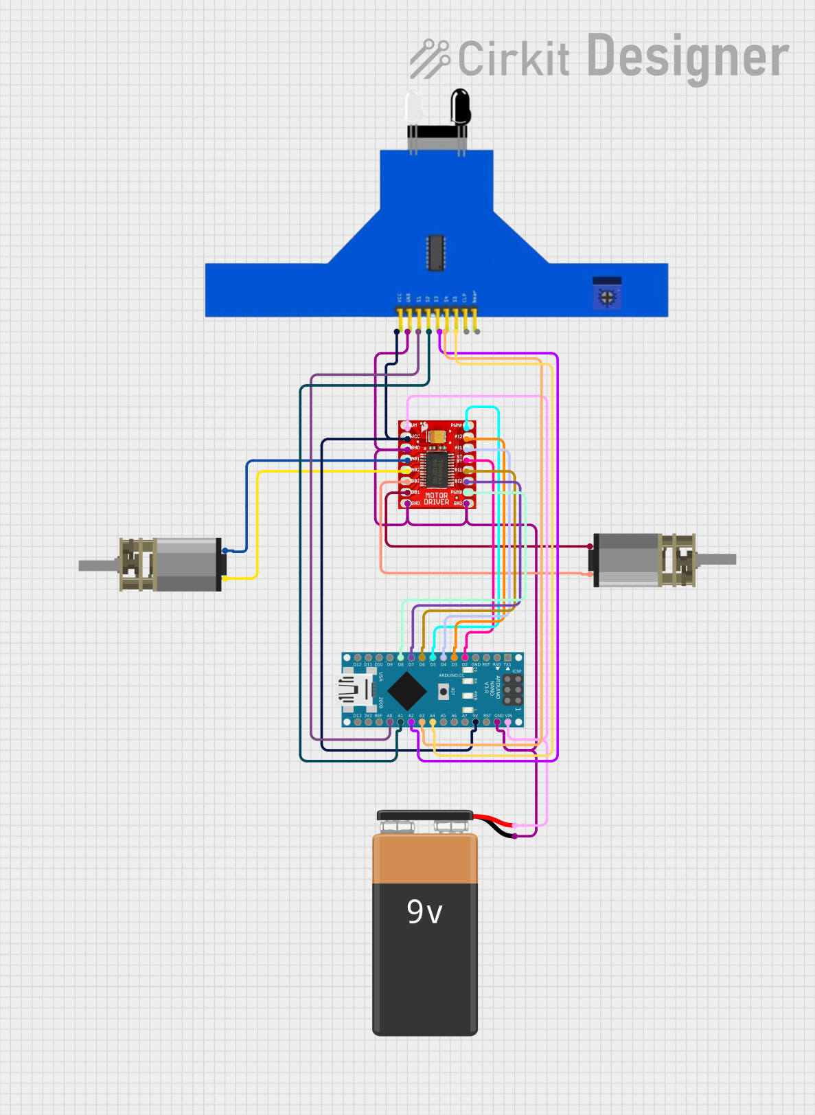
Explore Projects Built with Motor Driver 1A Dual TB6612FNG
Technical Specifications
Key Technical Details
- Motor Supply Voltage (VM): 4.5 V to 13.5 V
- Logic Supply Voltage (VCC): 2.7 V to 5.5 V
- Output Current: 1 A per channel (1.2 A peak)
- Standby Control to Save Power
- Built-in Thermal Shutdown Circuit and Low Voltage Detecting Circuit
- Maximum Power Dissipation: 2.0 W (@70°C)
Pin Configuration and Descriptions
| Pin Number | Pin Name | Description |
|---|---|---|
| 1 | VM | Motor voltage supply, connects to the motor power source |
| 2 | VCC | Logic voltage supply, connects to the control board (e.g., Arduino) |
| 3 | GND | Ground connection |
| 4 | STBY | Standby pin (active low) |
| 5 | AIN1 | Input 1 for motor A |
| 6 | AIN2 | Input 2 for motor A |
| 7 | BIN1 | Input 1 for motor B |
| 8 | BIN2 | Input 2 for motor B |
| 9 | PWMA | PWM input for motor A |
| 10 | PWMB | PWM input for motor B |
| 11 | AOUT1 | Output 1 for motor A |
| 12 | AOUT2 | Output 2 for motor A |
| 13 | BOUT1 | Output 1 for motor B |
| 14 | BOUT2 | Output 2 for motor B |
Usage Instructions
Connecting the Motor Driver to a Circuit
- Connect the VM pin to your motor power supply (4.5 V to 13.5 V).
- Connect the VCC pin to the logic power supply (2.7 V to 5.5 V), which is typically the power output from your control board.
- Connect the GND pin to the common ground of your power supply and control board.
- Connect the STBY pin to a digital output on your control board to enable or disable the motor driver.
- Connect AIN1 and AIN2 to digital outputs on your control board to control motor A's direction.
- Connect BIN1 and BIN2 to digital outputs on your control board to control motor B's direction.
- Connect PWMA and PWMB to PWM-capable digital outputs on your control board to control the speed of motors A and B, respectively.
- Connect AOUT1 and AOUT2 to the two terminals of motor A, and BOUT1 and BOUT2 to the two terminals of motor B.
Important Considerations and Best Practices
- Ensure that the power supply voltage does not exceed the recommended range to prevent damage to the motor driver.
- Use a common ground for all components in the circuit to avoid potential issues with signal integrity.
- When using PWM to control motor speed, ensure that the frequency is within the acceptable range for the TB6612FNG.
- Avoid running the motor driver at its peak current for extended periods to prevent overheating.
Example Code for Arduino UNO
// Define the connections to the Arduino
const int motorAin1 = 2;
const int motorAin2 = 3;
const int motorApwm = 9; // Must be a PWM pin
const int motorBin1 = 4;
const int motorBin2 = 5;
const int motorBpwm = 10; // Must be a PWM pin
const int standbyPin = 6;

void setup() {
  // Set all the motor driver pins as outputs
  pinMode(motorAin1, OUTPUT);
  pinMode(motorAin2, OUTPUT);
  pinMode(motorApwm, OUTPUT);
  pinMode(motorBin1, OUTPUT);
  pinMode(motorBin2, OUTPUT);
  pinMode(motorBpwm, OUTPUT);
  pinMode(standbyPin, OUTPUT);

  // Take the motor driver out of standby
  digitalWrite(standbyPin, HIGH);
}

void loop() {
  // Drive motor A forward at full speed
  digitalWrite(motorAin1, HIGH);
  digitalWrite(motorAin2, LOW);
  analogWrite(motorApwm, 255); // Full speed

  // Drive motor B backward at half speed
  digitalWrite(motorBin1, LOW);
  digitalWrite(motorBin2, HIGH);
  analogWrite(motorBpwm, 127); // Half speed

  delay(2000); // Run for 2 seconds

  // Stop both motors
  digitalWrite(motorAin1, LOW);
  digitalWrite(motorAin2, LOW);
  digitalWrite(motorBin1, LOW);
  digitalWrite(motorBin2, LOW);

  delay(1000); // Stop for 1 second
}
Troubleshooting and FAQs
Common Issues
- Motor not running: Check connections, ensure the standby pin is set high, and verify that the power supply is within the specified range.
- Overheating: Reduce the load on the motor or improve ventilation around the motor driver.
- Inconsistent motor speed or direction: Ensure PWM signals are being sent correctly and that the logic connections are secure.
Solutions and Tips for Troubleshooting
- Always double-check wiring, especially the power connections and ground.
- Use a multimeter to verify that the correct voltages are present at the motor driver pins.
- If using PWM, start with a low duty cycle and gradually increase to find the optimal speed range for your application.
FAQs
Q: Can I use the TB6612FNG to drive a stepper motor? A: Yes, the TB6612FNG can be used to drive a bipolar stepper motor by controlling the current in the coils with the input and PWM pins.
Q: What should I do if the motor driver gets too hot? A: Ensure that the current draw is within the specified limits, check for any shorts, and consider adding a heat sink or improving airflow around the driver.
Q: Can I control the TB6612FNG with a microcontroller other than an Arduino? A: Absolutely, any microcontroller with digital output capability can be used to control the TB6612FNG, as long as it operates within the logic voltage range.