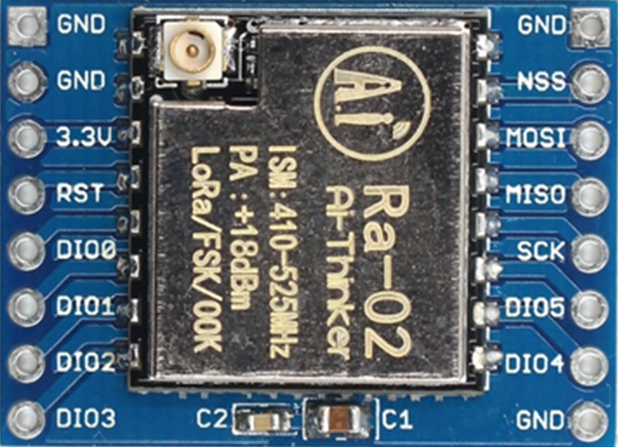
How to Use Ra02: Examples, Pinouts, and Specs
Introduction
The Ra02 is a resistor manufactured by Lora, designed for use in electronic circuits to limit current flow, divide voltages, and provide precise resistance values. It is a fundamental passive component used in a wide range of applications, from simple circuits to complex electronic systems. The Ra02 is characterized by its resistance value, tolerance, and power rating, making it suitable for both general-purpose and specialized applications.
Explore Projects Built with Ra02
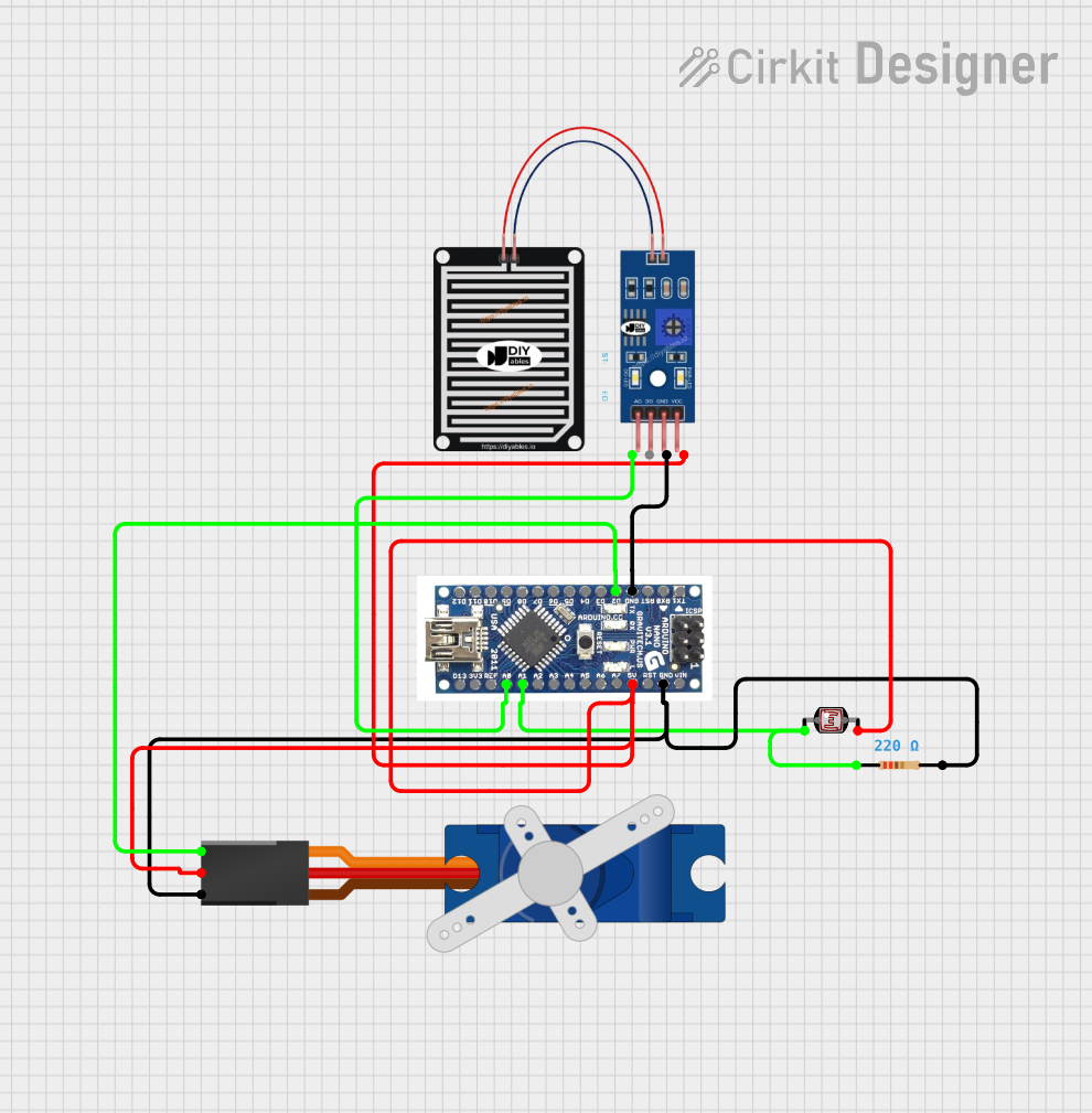
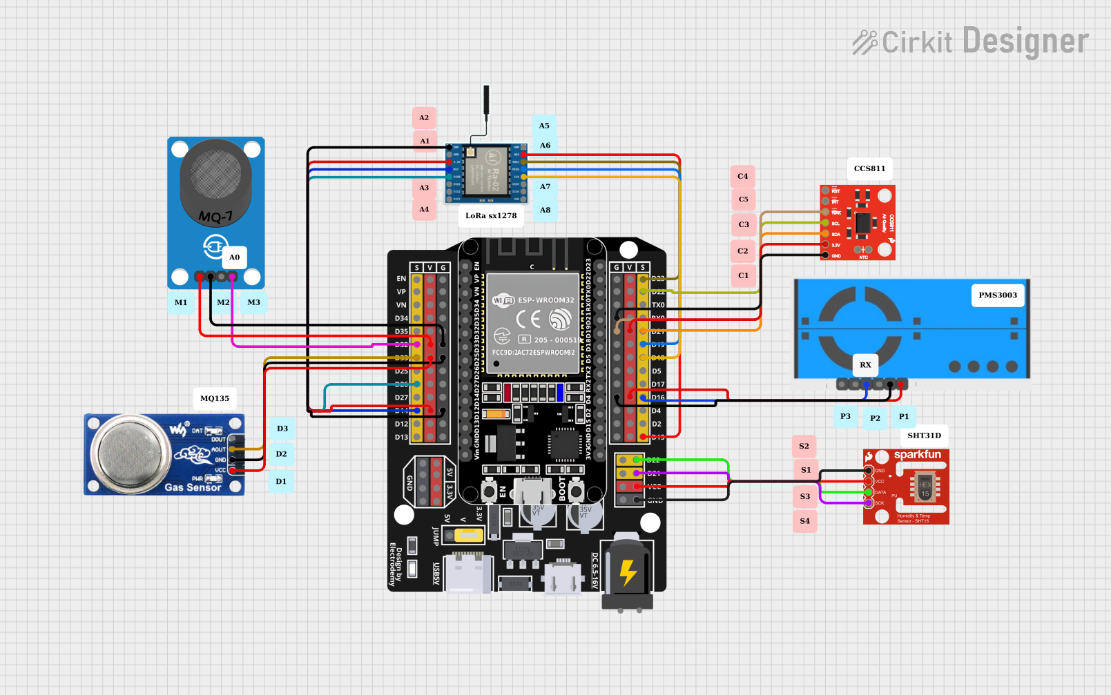
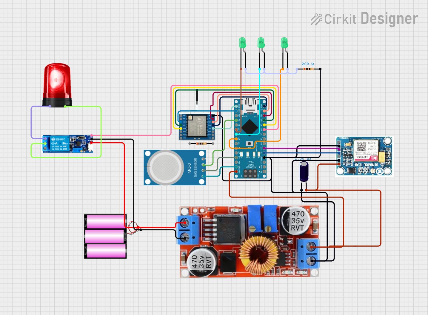
Explore Projects Built with Ra02
Common Applications and Use Cases
- Current limiting in LED circuits
- Voltage division in sensor circuits
- Pull-up or pull-down resistors in digital circuits
- Biasing resistors in transistor circuits
- Signal conditioning in analog circuits
Technical Specifications
The Ra02 resistor is available in various resistance values, tolerances, and power ratings. Below are the key technical details:
General Specifications
| Parameter | Value/Range |
|---|---|
| Resistance Range | 1 Ω to 10 MΩ |
| Tolerance | ±1%, ±5% |
| Power Rating | 0.125 W (1/8 W), 0.25 W (1/4 W) |
| Temperature Coefficient | ±100 ppm/°C to ±200 ppm/°C |
| Operating Temperature | -55°C to +155°C |
| Package Type | Axial or Surface Mount (SMD) |
Pin Configuration and Descriptions
For through-hole (axial) resistors:
| Pin Number | Description |
|---|---|
| Lead 1 | Connects to one side of the circuit |
| Lead 2 | Connects to the other side of the circuit |
For surface-mount (SMD) resistors:
| Pin Number | Description |
|---|---|
| Terminal 1 | Connects to one side of the circuit |
| Terminal 2 | Connects to the other side of the circuit |
Usage Instructions
How to Use the Ra02 in a Circuit
- Determine the Required Resistance Value: Use Ohm's Law (V = IR) to calculate the resistance needed for your application.
- Select the Appropriate Power Rating: Ensure the resistor's power rating exceeds the power it will dissipate in the circuit. Power dissipation is calculated as ( P = I^2R ) or ( P = V^2/R ).
- Place the Resistor in the Circuit:
- For axial resistors, insert the leads into the PCB holes and solder them.
- For SMD resistors, place the component on the PCB pads and solder it using reflow or hand-soldering techniques.
- Verify Connections: Double-check the resistor's placement and ensure it is connected to the correct points in the circuit.
Important Considerations and Best Practices
- Avoid Overloading: Do not exceed the resistor's power rating to prevent overheating or damage.
- Tolerance Selection: Use resistors with tighter tolerances (e.g., ±1%) for precision applications.
- Temperature Effects: Consider the temperature coefficient for applications with significant temperature variations.
- Series and Parallel Configurations: Combine resistors in series or parallel to achieve non-standard resistance values.
Example: Using Ra02 with an Arduino UNO
The Ra02 can be used as a pull-up resistor in an Arduino UNO circuit. Below is an example code snippet:
// Example: Using Ra02 as a pull-up resistor with a push button
const int buttonPin = 2; // Pin connected to the push button
const int ledPin = 13;   // Pin connected to the onboard LED

void setup() {
  pinMode(buttonPin, INPUT_PULLUP); // Enable internal pull-up resistor
  pinMode(ledPin, OUTPUT);          // Set LED pin as output
}

void loop() {
  int buttonState = digitalRead(buttonPin); // Read the button state

  if (buttonState == LOW) { // Button pressed (LOW due to pull-up resistor)
    digitalWrite(ledPin, HIGH); // Turn on the LED
  } else {
    digitalWrite(ledPin, LOW);  // Turn off the LED
  }
}
Troubleshooting and FAQs
Common Issues
Resistor Overheating:
- Cause: Exceeding the power rating.
- Solution: Use a resistor with a higher power rating or reduce the current/voltage in the circuit.
Incorrect Resistance Value:
- Cause: Misreading the color code or using the wrong resistor.
- Solution: Verify the resistance value using a multimeter or double-check the color code.
Circuit Malfunction:
- Cause: Poor soldering or incorrect placement.
- Solution: Inspect solder joints and ensure proper connections.
FAQs
Q1: Can I use the Ra02 in high-frequency circuits?
A1: Yes, but consider the parasitic inductance and capacitance of the resistor, especially for SMD types.
Q2: How do I calculate the total resistance of multiple Ra02 resistors in parallel?
A2: Use the formula ( 1/R_{total} = 1/R_1 + 1/R_2 + ... + 1/R_n ).
Q3: What happens if I use a resistor with a lower power rating than required?
A3: The resistor may overheat, degrade, or fail, potentially damaging the circuit.
By following this documentation, users can effectively integrate the Ra02 resistor into their electronic projects while avoiding common pitfalls.